


14628 Central Blvd,
Chino, CA91710
tel:909.597.7588, fax:909.597.1939
© Copyright 2011 Acnodes, Inc.
All rights reserved. Product description and product specifications
are subject to change without notice. For latest product information,
please visit Acnodes’ web site at www.acnodes.com.
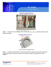
PC 6408
8” Fanless Panel PC
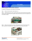
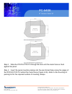
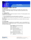
Step 4: Align the wall-mounting bracket screw holes with the pilot holes.
Step 5: Secure the mounting-bracket to the wall by inserting the retention screws into
the four pilot holes and tightening them (see Figure 3-11).
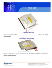
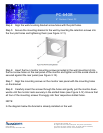
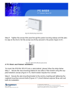
Step 6: Insert the four monitor mounting screws provided in the wall mounting kit into
the four screw holes on the real panel of the monitor and tighten until the screw shank is
secured against the rear panel (see Figure 3-12).
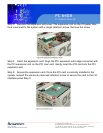
Step 7: Align the mounting screws on the monitor rear panel with the mounting holes
on the bracket.
Step 8: Carefully insert the screws through the holes and gently pull the monitor down-
wards until the monitor rests securely in the slotted holes (see Figure 3-12). Ensure that
all four of the mounting screws fit snuggly into their respective slotted holes.
NOTE:
In the diagram below the bracket is already installed on the wall.