


14628 Central Blvd,
Chino, CA91710
tel:909.597.7588, fax:909.597.1939
© Copyright 2011 Acnodes, Inc.
All rights reserved. Product description and product specifications
are subject to change without notice. For latest product information,
please visit Acnodes’ web site at www.acnodes.com.
PC 6408
8” Fanless Panel PC
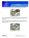
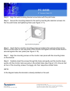
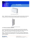
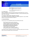
Step 9: Secure the panel PC with the wall-mounting kit. To do this, stick the protective
cushion to the wall-mounting kit first. Then, put the wall-mounting kit on the top panel of
the panel PC. Carefully mark the location of the wall-mounting kit screw holes on the
wall. Drill a pilot hole at the marked location on the wall. Secure the wall-mounting kit to
the wall by inserting a retention screw into the pilot hole on the wall (Figure 4-30). This
step is to avoid the panel PC being pushed apart from the wall-mounting bracket acci-
dentally.
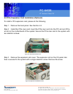
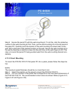
4.11.2 Panel/ Mounting
To mount the PC5153/ PC5173 flat panel PC into a panel, please follow the steps be-
low.
NOTE:
The maximum panel thickness should be no more than 6 mm.
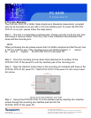
Step 1: Select the position on the panel to mount the PC5153/ PC5173.
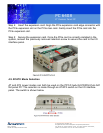
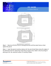
Step 2: Cut out a section of the panel that corresponds to the rear panel dimensions of
the PC5153/ PC5173. The recommended cutout sizes are shown below (Figure 4-31,
Figure 4-32 and Figure 4-33).