


ADCP-90-250
Issue 1, November 1996
Page 3
1996, ADC Telecommunications, Inc.
A.Functional Description
1.02
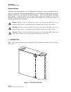
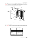
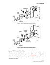
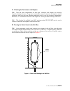
The FTD1 36-Fiber Wall Box (Figure 1) is designed to provide a wall-mounted, or rack-
mounted, secure, fiber cable terminal for use in small to medium-sized fiber networks and
customer premises applications. The wall box can accommodate up to four OSP cables and
contains provisions for splicing and terminating 36 singlemode fiber circuits.
1.03
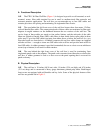
The area behind the left front cover of the wall box houses three four-meter, 12-fiber,
soft wall bundle fiber cables. The connectorized ends of these cables are terminated to fiber optic
adapters in angled retainers on the bulkhead between the two sections of the wall box. The
service loops of these cables are stored on four radius limiters, and the stub ends of the cable
fibers are spliced to Outside Plant (OSP) cable fibers in heat shrink fusion splice chips in three
splice trays. Up to four OSP cables can enter from either above or below the wall box (i.e., two
from above and two from below). A Hubbell connector kit and four cable clamps are supplied
with the wall box — enough to secure one OSP cable to the wall box and provide strain relief for
four OSP cables. A rubber grommet is provided (unattached) for use as a dust cover at whichever
corner (top or bottom) is not used for cable entrance.
1.04
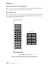
The area behind the right front cover of the wall box is used for terminating 3mm
singlemode patch cords to the adapters. The patch cords can enter from either above or below the
wall box. A rubber grommet is used as a dust cover at the panel opening that is not used for
patch cord entry.
B.Physical Description
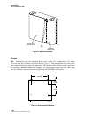
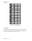
1.05
The wall box is 19 inches (48.26 cm) wide, 10 inches (25.4 cm) high, and 4.76 inches
(12.1 cm) deep, and is constructed of heavy gauge aluminum, painted putty white. Both hinged
front covers are equipped with pull handles and key locks. Some of the physical features of the
wall box are pointed out in Figure 2.