


ADCP-90-250
Issue 1, November 1996
Page 8
1996, ADC Telecommunications, Inc.
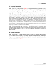
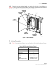
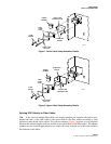
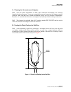
CONNECTOR
BODY
BUSHING
SPLIT
RING
COMPRESSION
NUT
0SP
CABLE
8993-A
HUBBELL
CONNECTOR
(ASSEMBLED)
CLINCH
NUT
Figure 6. Hubbell Connector Kit
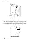
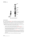
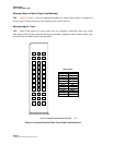
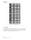
Cable Clamp Kits
2.07
The cable clamp kits (Figures 7 and 8) are installed on-site to separate the incoming OSP
cable fibers for easier management within the wall box. Each cable clamp kit includes a
mounting plate (upper or lower; i.e., high or low), a clamp cover plate, two rubber yokes, a set of
five rubber grommets, and associated hardware (two mounting screws and two clamp screws).
Note
: The breakout lengths of the OSP cable fibers should be long enough to extend
2.5 times around the radius limiters that surround the splice tray.
1. Mount the selected cable clamp mounting plate (either high or low) using two
#4 mounting screws into the rear panel of the wall box per Figure 7 or Figure 8.
2. Select a grommet which (when placed around the cable), has a gap within the range of
nearly zero to 0.30 inch (0 to 8 mm). If the outer diameter of the cable is 0.7 to 0.8 inch
(1.78 to 2.03 cm), no grommet is required.
3. Assemble the cable clamp components as shown in Figure 7 or 8: secure the cable and
grommet (if used) between the two cable clamp yokes, then place the clamp plate over
the outer yoke and secure the yokes and cable to the mounting plate with two long
screws. Be sure the cable sheath extends approximately 0.75 inch (1.9 cm) beyond the
cable clamp.
4. Repeat steps 1 through 3 as necessary to install additional cable clamp kits.