


ADCP-90-250
Issue 1, November 1996
Page 7
1996, ADC Telecommunications, Inc.
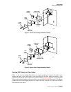
B.Rack Mounting the Wall Box
2.03
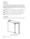
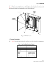
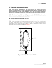
The FTD1 36-Fiber Wall Box can be rack-mounted in a 19-inch frame. This is
accomplished by inserting a #12 screw through the 1/4-inch slots in each corner of the rear panel
of the wall box, into the threaded mounting holes in the frame. The upper two vertical mounting
slots are approximately one-half inch long; those in the bottom corners are one inch long.
C.Installing Wall Box Components
2.04
Additional components available for use in the wall box include Hubbell connector kits,
lower cable clamp kits, upper cable clamp kits; grounding kits; three splice trays, and a sheet of
fiber designation labels.
Clamping OSP Cables
2.05
OSP cables can be clamped to the wall box using a Hubbell connector kit and cable
clamp assembly.
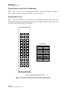
Hubbell Connector Kit
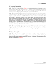
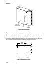
2.06
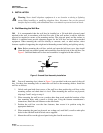
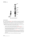
The Hubbell connector kit (Figure 6) is installed on-site to secure an OSP cable to the
bottom (or top) of the wall box. Each Hubbell connector kit includes all the parts necessary to
secure an OSP fiber cable to the wall box.
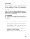
1. Using the cinch nut on the inside, mount the Hubbell connector in the upper or lower left
corner of the wall box.
2. Remove the compression nut, split ring and bushing from the body of the Hubbell
connector, then place them (in that order) over the end of the OSP cable onto the cable
jacket.
3. Route the OSP cable through the Hubbell connector into the wall box, then strip the
outer sheath of the end of the cable to expose the inner fibers or subunits.
4. After adjusting and clamping the OSP cable with a cable clamp kit (below), slide the
compression nut, split ring and bushing up (or down) the cable and thread the
compression nut onto the connector body and tighten it securely.