


ADCP-90-250
Issue 1, November 1996
Page 4
1996, ADC Telecommunications, Inc.
8515-A
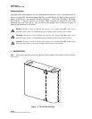
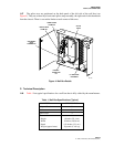
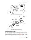
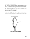
ACCESS COVER
TO CABLE SERVICE
LOOPS, SPLICES, ETC.
KEY
LOCKS
CONNECTOR
ACCESS COVERS
Figure 2. Wall Box Features
Chassis
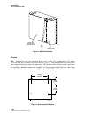
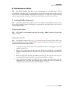
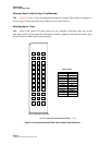
1.06
The wall box has four mounting holes at the corners of a rectangle that is 8.5 inches
(21.6 cm) high and 14 inches (35.6 cm) wide (see Figure 3). The rear panel has two slots for the
splice strap assembly that retains the splice trays. The left side of the wall box includes provisions
for mounting a Hubbell connector kit (supplied) and four (staggered, high and low) cable clamp
kits; also included are provisions (kits) for grounding the OSP cables to the wall box.
8516-B
4.25 IN.
(10.8 CM)
14.00 IN.
(35.6 CM)
8.5 IN.
(21.6 CM)
Figure 3. Mounting Hole Pattern