


ADCP-90-250
Issue 1, November 1996
Page 5
1996, ADC Telecommunications, Inc.
1.07
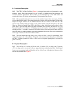
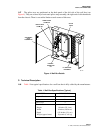
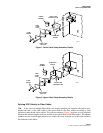
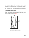
The splice trays are positioned on the back panel of the left side of the wall box (see
Figure 4). They are secured by a horizontal splice strap assembly, the right end of which unhooks
from the chassis. There is one radius limiter at each corner of this area.
8517-B
SPLICE
TRAYS
LOWER CABLE
CLAMP KIT
UPPER CABLE
CLAMP KIT
GROUNDING
STUD
ASSEMBLIES
HUBBELL
CONNECTOR
KIT
FC ADAPTERS/
RETAINERS
Figure 4. Wall Box Details
C.Technical Description
1.08
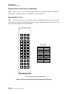
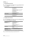
Table 1 lists typical specifications for a wall box that is fully cabled by the manufacturer.
Table 1. Wall Box Specifications (Typical)
PARAMETER SPECIFICATION
Adapters/Retainers 36
Cables 3
Splice Trays 3
Dimensions:
Height 10 inches (25.4 cm)
Width 19 inches (48.26 cm)
Depth 4.76 inches (12.1 cm)
Weight (approximate) 30 pounds (13.61 kg)