


LTPH-UM-1109-01, Issue 1 Testing
H2TU-C-231 List 2 January 9, 2002 47
• COL? = dual loopback at H2TU-C.
• RUL? = dual loopback at H2TU-R.
4 Press SEL to activate the selected loopback. The previous loopback is terminated.
Once a loopback is selected and activated, the loopback stays active until it times out (based on the LBTO setting).
When a loopback times out, the display returns to the normal display mode.
You can terminate loopbacks manually and exit the MAN LPBK mode by simultaneously pressing the MODE and
SEL pushbuttons for 3 or more seconds. If no loopback is active, the MAN LPBK mode automatically terminates
after 30 seconds.
All loopbacks (except dual loopbacks) can be initiated by inband commands in the DS1 payload. Loopbacks can
also be initiated by a command from the HiGain HDSL2 system (front-panel pushbuttons or maintenance screen
selections). Therefore, whenever a loopback is active, the method by which it was activated is indicated in the
Monitor screen by the annotation HG or PL adjacent to the identified loopback. For example, NREM-HG
indicates that the loopback was initiated by the HiGain HDSL2 system.
LOOPBACK TEST PROCEDURES
The following sections provide step-by-step test procedures for verifying the integrity of the HDSL2 channels at
every module location as well as the DS1 channels to the customer and the local DSX-1 interface.
General Troubleshooting Tips
If trouble is encountered on the DSX-1 interface of the H2TU-C-231, verify that the:
• H2TU-C is making a positive connection with its mounting-assembly (shelf) connector.
• H2TU-C internal equalizer is set to the correct distance range per Table 6 on page 18. All equalizers should
be set to the distance from the DSX-1 to the shelf.
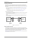
The transmit and receive DSX-1 ports have splitting access jacks and miniature 210-series, bridging jacks as
shown in Figure1onpage3. Connecting one cable between the two bridging jacks and another between the two
LINE jacks splits the IN and OUT and creates metallic loopbacks towards both the DSX-1 and the H2TU-C-231.
If separate plugs are inserted into both LINE jacks with the other end disconnected, the BRG jacks can be used to
send and receive test patterns towards the DSX-1.
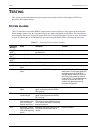
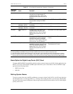
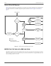
GNLB Test Procedures
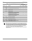
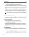
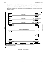
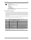
Figure28onpage48is a graphical representation of the various loopback configurations with the associated
GNLB commands shown. Also, refer to Table16onpage44foradescriptionofthesecommands.
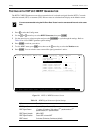
To perform the GNLB loopback test procedure:
1 Have the CO tester send the NREM (3-in-7) inband loopup code for 5 seconds. You should be able to observe
the NREM message on the front-panel display. (The Status LED on the front panel should be green, and the
loopback mode should also be identified on the Monitor screen.)
2 Have the CO tester transmit a DS1 test signal towards the H2TU-C-231 and verify that the returned (looped)
signal to the test set is error-free.
3 If step 2 fails, have the CO tester transmit the 3-in-5 inband loopdown code.
SMJK loopback commands are only activated by inband commands. Dual loopback commands
are only activated by the front-panel pushbuttons or maintenance screen selections.