


LTPH-UM-1031-03, Issue 3 Testing
H4TU-C-319 List 1 September 12, 2003 43
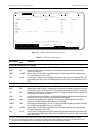
RRAI Remote RAI—Remote
Alarm Indication at the
H4TU-R (Net signal
has errors.)
Indicates an RAI alarm (yellow) from the CPE
with errors from the line unit or network.
Cannot be inhibited.
xxx-DBER DS1 Bit Error Rate The DS1 BER has exceeded the set 24-hour
threshold limit of approximately 10
-6
. (xxx
denotes either TUC or TUR. If TUC and TUR
occur at the same time, then TUC displays.)
Select DIS for the DBER system option.
xxx-LOF Loss of Frame The DS1 input does not contain the ESF or SF
frame pattern setting of the FRMG option.
(xxx denotes either TUC or TUR. If TUC and
TUR occur at the same time, then TUC
displays.)
Change FRMG option to AUTO or UNFR.
PRMN Performance Report
Messaging - Near End
H4TU-R PRM-NE BER threshold has been
exceeded.
Set DBER threshold to DIS.
PRMF Performance Report
Messaging - Far End
H4TU-R PRM-FE BER threshold has been
exceeded.
Set DBER threshold to DIS.
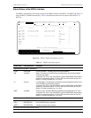
xxxx-HBRx
(d)
HDSL4 Block Error
Rate
The HDSL4 BER has exceeded the set
threshold limits of 10
-6
or 10
- 7
.
xxxx denotes TUC, TUR, or first
(DU1U/DU1D) or second (DU2U/DU2D)
doubler HDSL4 upstream or downstream
interface. If TUC and TUR occur at the same
time, then TUC displays. The single x
indicates Loop 1 or Loop 2.
Select NONE for the HBER system option.
xxxx-MALx
(d)
Margin Alarm The margin on the HDSL4 loop has dropped
below the minimum threshold value set for the
system.
xxxx denotes TUC, TUR, or first
(DU1U/DU1D) or second (DU2U/DU2D)
doubler HDSL4 upstream or downstream
interface. If TUC and TUR occur at the same
time, then TUC displays. The single x
indicates Loop 1 or Loop 2.
Set the Margin Alarm Threshold option to
zero.
xxxx-LAx
(d)
Loop Attenuation The attenuation on the HDSL4 loop has
exceeded the maximum value set for the
HDSL4 loop attenuation threshold.
xxxx denotes TUC, TUR, or first
(DU1U/DU1D) or second (DU2U/DU2D)
doubler HDSL4 upstream or downstream
interface. If TUC and TUR occur at the same
time, then TUC displays. The single x
indicates Loop 1 or Loop 2.
Set the HDSL4 Loop Attenuation
Threshold option to zero.
(a) The message, ALRM, displays prior to any alarm message.
(b) Message displays repeatedly as long as the alarm condition exists and is not included in the priority order.
(c) When the HDSL4 loop loses sync word (LOSW), a system alarm condition exists. However, since the H4TU-C-319 enters the
acquiring mode, the front-panel status LED flashes red, and the ACQ or SIG message displays instead of the ALRM message.
(d) Only these alarms assert the System Alarm bus on pin H of the card-edge connector, if the ALM option is set to enabled.
Table 15. Front-Panel System Alarms (Continued)
Front-Panel
Message
(a)
Alarm Description To Inhibit: