


Appendix A - Specifications LTPH-UM-1031-03, Issue 3
62 September 12, 2003 H4TU-C-319 List 1
H4TU-C-319 CARD-EDGE CONNECTOR
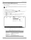
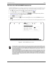
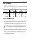
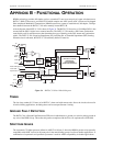
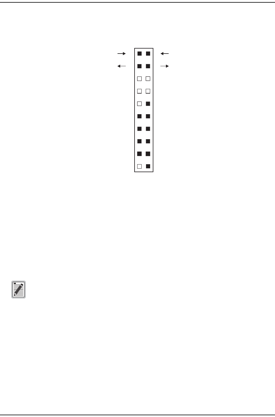
Figure 32 shows the card-edge connectors on the H4TU-C-319. Active pins are highlighted in black.
Figure 32. H4TU-C-319 Card-Edge Connector
Network Management Control Bus
The H4TU-C provides a Network Management Control Bus on pin 7 of the card-edge connector. This allows the
various Management System protocols to manage the H4TU-C through the HMU-319. Whenever the H4TU-C is
under management, the MNGD message displays periodically on the front-panel display.
Fuse Alarm
Pin 10 on the card-edge connector is a Fuse Alarm that is driven to -48 Vdc whenever its onboard fuse opens. It
emulates the function of the Fuse Alarm output from pin 10 on normal, high-density (HD) repeaters. Pin 10 is
connected to pin 5 of the 1184 Alarm Card (slot 1 in the HD shelf) and causes the 1184 Fuse ALM LED to light
when the pin 10 signal is activated. Its normally floating output must never be driven above ground or below
-80 V. It can sink a current of 10 mA. The H4TU-C does not support the BPV function (Pin E) of normal HD
repeaters.
Some H4TU-C-319 features are affected when it is under management. Consult the management
unit practice for further information (see “Appendix D - Product Support” on page 66).
3
4
5
6
C
D
E
F
H7
8
J
9
K
10
L
GND
HDSL4-L1Tip
HDSL4-L1Ring
SystemAlarm** ManagementBus**
Frame GND
-48 Vdc
Fuse Alarm*
(Do notuse)
1
A
(IN)DSX-1Tip
DSX-1Ring(IN)
2
B
(OUT)DSX-1Tip1
DSX-1Ring1(OUT)
Fuse Alarm
System Alarm and Management Bus (reserved)
Normal = Floating (0 to -60 Vdc maximum)
Activated = -48 Vdc (10 mA maximum)
*
**
HDSL4-L2Tip
HDSL4-L2Ring