


LTPH-UM-1031-03, Issue 3 Appendix A - Specifications
H4TU-C-319 List 1 September 12, 2003 63
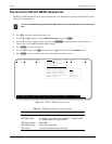
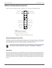
System Alarm Output Pin
Pin H on the card-edge connector (see Figure 33 on page 63) is the H4TU-C-319 System Alarm output pin. The
following notes apply to Pin H:
• Pin H replaces the Local Loss of Signal (LLOS) on normal high-density (3192) repeaters.
• The normally floating output of Pin H can connect to pin 1 of the 1184 or 3192-9F Alarm Card in position 29
of the High Density (HD) shelf.
• The H4TU-C forces pin H to +5Vdc (maximum of 10 mA) for a system alarm condition. Pin H then remains
at +5 Vdc for the duration of the alarm condition.
• If the Wescom 1184 Alarm Card is installed in the shelf, its LOS LED lights for every minor alarm
(MNRALM).
• The H4TU-C Status LED flashes red for the duration of a system alarm condition.
• Setting the ALM option to DIS only prevents the system alarm bus on Pin H from being activated for a system
alarm event. The Status LED still flashes red and the ALRM message still displays.
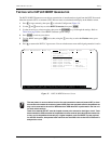
CRAFT PORT
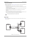
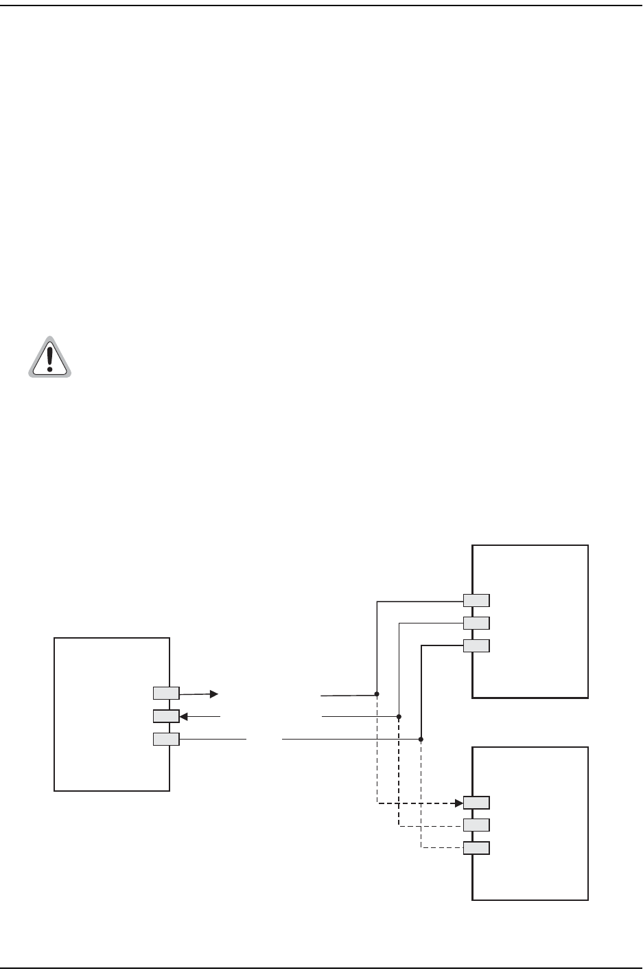
Figure 33 shows the pinout for the craft port connection and its connection to a DB-9 or DB-25 connector on a
maintenance terminal.
Figure 33. RS-232 Craft Port Pinouts
Pin H must never be taken above +5 Vdc or below -60 Vdc.
H4TU-C-319
DB-9 Connector
(DCE)
RD (Receive Data)
TD (Transmit Data)
2
3
5
DB-9 Connector
(DTE)
DB-25 Connector
(DTE)
2
3
5
3
2
7
GND
Terminal
Terminal