


LTPH-UM-1237-04 Overview
HRM-238 List 1 July 21, 2004 3
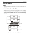
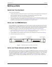
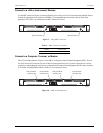
Recommended Network Setup for 3190 Type Shelves
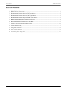
The configuration shown in Figure 3 is the recommended setup for 3190 type mechanics shelves. Position the
HRM-238 shelf below the 3190 type shelves. This limits the distance for the wire leads between the connectors
for the management units and the line units they manage. Figure 3 shows the HRM-238 shelf from the rear view
with the A-side connectors on the right and the B-side connectors on the left. The leads from the HRM-238 shelf
connector attach to the Network Management Agent (NMA) pins on the rear of the 3190-type mechanics shelves
for each line unit managed. The NMA pin on 3190 type chassis is pin 7.
Figure 3. Recommended Network Setup for 3190 Type Shelves
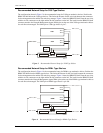
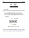
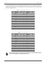
Recommended Network Setup for DDM+ Type Shelves
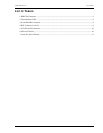
The configuration shown in Figure 4 is the recommended setup for DDM+ type mechanics shelves. Position the
HRM-238 shelf below the DDM+ type shelves. This limits the distance for the wire leads between the connectors
for the management units and the line units they manage. Figure 4 shows the HRM-238 shelf from the rear view
with the A-side connectors on the right and the B-side connectors on the left. The leads from the HRM-238 shelf
connector attach to the Network Management Agent (NMA) pins on the rear of the DDM+ type mechanics shelves
for each line unit managed. The NMA pin on DDM+ type chassis is pin 104.
Figure 4. Recommended Network Setup for DDM+ Type Shelves
3190
HRM-238
-48V A
-48V A
-48V B
-48V B
Network B Network A
TB1
CO -48V
Supply
H0544-C
3190
NMA 1 to 28 B
NMA 1 to 28 A
NMA 1 to 28 B
NMA 1 to 28 A
DDM+
HRM-238
-48V A
-48V A
-48V B
-48V B
Network B Network A
TB1
CO -48V
Supply
H0544-D
DDM+
NMA 1 to 28 B
NMA 1 to 28 A
NMA 1 to 28 B
NMA 1 to 28 A