


Installation LTPH-UM-1237-04
10 July 21, 2004 HRM-238 List 1
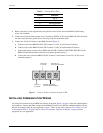
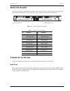
Use a null modem connector for cross-over cabling when attaching a device that is not configured as DCE (such
as terminals or computers running terminal emulation software) to these connectors. Table 5 shows the pinouts
for the two AUX ports (one port for each management unit). Table 6 shows the pinouts for the two OS ports (one
port for each management unit).
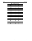
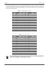
Table 5. AUX P3 and P5 Connectors
Pin Description I/O Pin Description I/O
1 N/C 14 N/C
2 AUX_TX O 15 N/C
3 AUX_RX I 16 N/C
4 N/C 17 N/C
5 N/C 18 N/C
6 AUX_DSR- I 19 N/C
7 LGND I 20 AUX_DTR- O
8 N/C 21 N/C
9 N/C 22 N/C
10 N/C 23 N/C
11 N/C 24 N/C
12 N/C 25 N/C
13 N/C
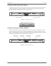
Table 6. OS Port P2 and P4
Pin Description I/O Pin Description I/O
1 N/C 14 N/C
2 OS_TX O 15 OS_TCLK I
3OS_RX I 16N/C
4 OS_RTS- O 17 OS_RCLK I
5 OS_CTS- I 18 N/C
6OS_DSR- I 19N/C
7 LGND I 20 OS_DTR- O
8 N/C 21 N/C
9 N/C 22 N/C
10 N/C 23 N/C
11 N/C 24 OS_TCLK I
12 N/C 25 N/C
13 N/C
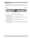
For further details about connecting to the AUX or OS connectors, consult the appropriate user
manual for the management unit and applicable software.