


LTPH-UM-1237-04 Installation
HRM-238 List 1 July 21, 2004 11
IDENTIFYING ALARMS
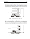
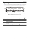
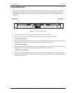
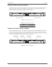
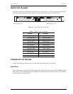
Alarm relay contacts for each management unit are on J13 and J14 (Figure 11). Install wiring between these pins
and an alarm monitoring device per local practice. Table 7 describes the alarm J13 and J14 pinouts.
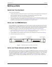
Figure 11. Alarm Relay Wire-Wrap Pins
TURNING UP THE SYSTEM
Perform the following procedures prior to installing the management unit(s) into the shelf.
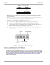
Insert Fuse
Insert an appropriately sized fuse(s) into the equipment bay fuse panel for the circuit(s) where the HRM-238 shelf
battery wire(s) were terminated. Refer to the appropriate management unit user manual for power consumption,
power dissipation, and current drain.
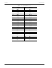
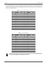
Table 7. Alarm J13 and J14 Pinouts
Pin Description Pin Description
1 CRIT_AUD_NC_A 13 MIN_AUD_NC_A
2 CRIT_AUD_COM_A 14 MIN_AUD_COM_A
3 CRIT_AUD_NO_A 15 MIN_AUD_NO_A
4 CRIT_VIS_NC_A 16 MIN_VIS_NC_A
5 CRIT_VIS_COM_A 17 MIN_VIS_COM_A
6 CRIT_VIS_NC_A 18 MIN_VIS_NO_A
7 MAJ_AUD_NC_A 19 SYS_ID_NC_A
8 MAJ_AUD_COM_A 20 SYS_ID_COM_A
9 MAJ_AUD_NO_A 21 SYS_ID_NO_A
10 MAJ_VIS_NC_A 22 EXT_ACO_A
11 MAJ_VIS_COM_A 23 LGND
12 MAJ_VIS_NO_A
Alarm relay pins (J13)Alarm relay pins (J14)
H0651-A