


LTPH-UM-1237-04 Installation
HRM-238 List 1 July 21, 2004 7
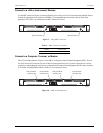
Connect NMA Wiring
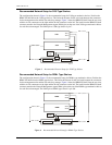
From the 50-pin Amphenol connector P1 and/or P6 (Figure 8), wire directly to the NMA pin 46 on the 220-type
shelf backplane for each line unit being managed. Route wires from the P1 and P6 connectors to the NMA
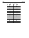
220-type mechanics shelves as shown in Figure 2 on page 2. Refer to Table 3 for P1 and P6 NMA connector
information.
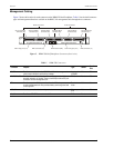
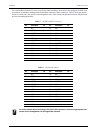
Figure 8. Connect NMA Wiring
1 Remove the plastic cover from the 50-pin Amphenol connector P1 and/or P6.
2 Install a 50-pin female plug into the connector. Separate the wires for each of the 50 pins.
For 220 type mechanics:
3 Wire wrap the corresponding NMA wire from the plug to the NMA pin 46 on the shelf for each line unit being
managed. The wire leads from the Amphenol plug can be up to 20 feet maximum.
For 3190 type mechanics:
4 Wire wrap the corresponding NMA wire from the plug to the NMA pin 7 on the shelf for each line unit being
managed. The wire leads from the Amphenol plug can be up to 20 feet maximum.
For DDM+ type mechanics:
5 Wire wrap or soldier (depending on chassis manufacturer) the corresponding NMA wire from the plug to the
NMA pin 104 on the shelf for each line unit being managed. The wire leads from the Amphenol plug can be
up to 20 feet maximum.
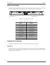
50-pin Amphenol
connector (P6)
50-pin Amphenol
connector (P1)
H0548-A