


Installation LTPH-UM-1237-04
12 July 21, 2004 HRM-238 List 1
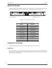
Verify Cabling
Verify the following:
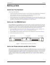
1Verify a minimum of -42 Vdc and a maximum of -56 Vdc between the following:
a -48 Vdc battery screw Terminal 1 and the battery common Terminal 3 (BATTERY RETURN)
b -48 Vdc battery screw Terminal 2 (when used) and the battery common Terminal 3 (BATTERY
RETURN)
2 Visually verify that all connections are securely terminated.
Secure Cabling
Tie the cable connectors to the back of the HRM-238 shelf using the tie wraps and mounting screws.
INSTALLING THE MANAGEMENT UNIT(S)
1 Install the management unit(s) into the HRM-238 shelf per procedures in the appropriate HMU-319 user
manual.
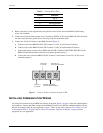
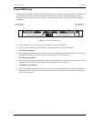
2 Loosen the security bracket screw, push down the security bracket, and re-tighten the screw (Figure 6 on
page 5).