


Overview LTPH-UM-1237-04
4 July 21, 2004 HRM-238 List 1
Management Cabling
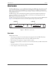
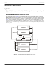
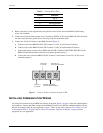
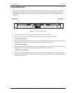
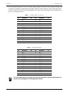
Figure 5 shows the location for each connector on the HRM-238 shelf backplane. Table 1 lists the shelf connector
types and management functions available to the HMU-319 management units through those connectors.
Figure 5. HRM-238 Shelf Backplane Connectors (back view)
Table 1. HRM-238 Connectors
Connector Purpose Type Gender
No. of
Pins
P1, P6 Provides connection from the HRM-238 shelf for the management
units to each individual card that they manage.
Amphenol
(CHAMP)
Male 50
P2, P3, P4, P5 Provides 4 connection points (two for each management unit) for a
terminal, computer, or modem. There is one AUX port and one OS port
connector for each management unit.
DB-25 Female 25
TB1 Provides separate -48 Vdc connection from the CO battery source
to each management unit. Also provides battery common ground and
a frame ground.
Terminal
block
N/A 6
J13, J14 Provides connection for alarm relay contacts. Wire-wrap
pins
Male 23
J1, J3 Provides a 10BASE-2 connection to a LAN. BNC Female 1
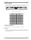
AUX port DB-25
connector (P5)
OS port DB-25
connector (P4)
BNC connector (J1
)
Alarm relay pins (J13)Terminal block (TB1)Alarm relay pins (J14) BNC connector (J3)
OS port DB-25
connector (P2)
50-pin Amphenol
connector (P6)
AUX port DB-25
connector (P3)
B
-s
id
e connectors
A
-s
id
e connectors
50-pin Amphenol
connector (P1)
H0545-A