


Installation LTPH-UM-1237-04
6 July 21, 2004 HRM-238 List 1
1 Remove the fuse(s) in the equipment bay fuse panel for the circuit(s) where the HRM-238 shelf battery
wire(s) will terminate.
2 Connect one end of the frame ground wire to Terminal 4 (FGND) on TB1 of the HRM-238 shelf and attach
the other end of the frame ground wire to the CO ground wire termination point.
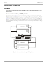
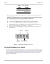
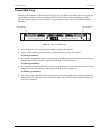
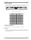
3 Connect the -48 Vdc CO battery to the HRM-238 shelf (Figure 7):
a Connect a wire to the HRM-238 shelf TB1 Terminal 1 (-48V_A) for Primary CO battery.
b Connect a wire to the HRM-238 shelf TB1 Terminal 2 (-48V_B) for Redundant CO battery.
c Connect the battery common wire to HRM-238 shelf TB1 Terminal 3 (BATTERY RETURN) of the
HRM-238 shelf and attach the other end to CO battery ground source(s).
d Connect the wire(s) from the HRM-238 TB1 Terminal 1 and Terminal 2 to the CO -48 Vdc power
termination point(s).
Figure 7. Connect -48 Vdc and Frame Grounds to TB1
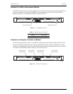
INSTALLING COMMUNICATION WIRING
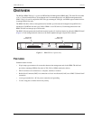
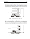
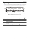
All wiring and connections for the HRM-238 shelf are on the back. Figure 5 on page 4 shows the shelf backplane
and connectors. Connect the NMA wiring from the HRM-238 shelf to each HiGain or Megabit Modem line unit
that will be managed using the steps beginning on page 7. Then, use the other connectors in “Connect to a LAN
or Interconnect Shelves” on page 9 and “Connect to a Computer, Terminal, or Modem” on page 9 that are
appropriate for your application.
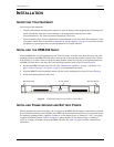
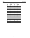
Table 2. Terminal Block (TB1)
Terminal Description
1 -48V_A
2 -48V_B
3 BATTERY RETURN
4 FGND
Terminal 1
to -48 Vdc
H0547-B
Terminal 4 to
frame ground (FGND
)
Terminal 2
to -48 Vdc
Terminal 3 to battery
common (Battery Return)