


ADCP-80-526 • Issue 6 • December 2006
Page 9
© 2006, ADC Telecommunications, Inc.
The alarm circuitry uses form C alarm relay dry contacts. During normal operation (power
applied and all fuses operational), the normally open (NO) contacts remain open and the
normally closed (NC) contacts remain closed. When a fuse fails on either bus or power to either
is lost, the NO contacts close creating a connection from NO and common and the normally
closed (NC) contacts open creating an open circuit between NC and common. The current
rating for each set of alarm relay contacts (either two or three sets of contacts are provided) is
110 Vdc/125 Vac maximum voltage, 1.0 Amp maximum switching current.
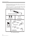
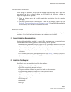
1.14 Alarm Contact Connectors
The fuse platform is available with either screw-down barrier terminal strips or wire wrap pins
for the alarm contact connections. The following describes both types of contact connections:
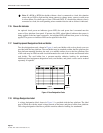
• Screw-down barrier terminal strip: Six terminals with 3-48 screws are mounted in a barrier
type terminal block. The terminals are on 0.25 inch (6.35 mm) centers with a maximum
distance between barriers (maximum connecting terminal width) of 0.20 inch (5.08 mm).
The alarm terminal strip has two sets of three terminals (NO, C, and NC) for use with two
alarm systems. The terminals can accept #16 to #30 AWG copper wire with insulation
stripped back. In selecting wire size, follow local code referring to the ampacity guidelines
provided in Appendix A of this manual.
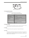
• Wire-wrap terminal block: Nine wire-wrap pins are mounted in a terminal block for both
buses. The alarm terminal block has three sets of three wire-wrap pins (NO, C, NC), for
use with three alarm systems. The wire-wrap pins can accept #22 to #26 AWG copper wire
with insulation stripped back. In selecting wire size, follow local code referring to the
ampacity guidelines provided in Appendix A of this manual.
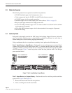
1.15 Fuse Alarm Indicators
A visual fuse alarm indicator (red LED) is provided on the front of each fuse holder module.
The fuse alarm indicator lights when any fuse in the corresponding fuse holder fails. The fuse
alarm indicator is off when all fuses in the fuse holder module are operational. Loss of power to
a bus will not cause the fuse alarm indicators corresponding to that bus to be lighted. For TPA
and KLM fuses, there is one fuse holder per fuse and, therefore, a fuse alarm indicator for each
fuse. For GMT fuses, there are four or ten fuses per fuse holder with a single fuse alarm
indicator for the entire set of fuses.
Note: If a KLM or KTM fuse holder without a fuse is connected to a load, this situation
causes the red LED to light and the alarm contacts to change states, same as would occur
in a fuse failure. For other types of fuses (TPA and GMT), if a fuse holder without a fuse is
connected to a load, the corresponding sensor remains inactive and no failure is indicated.
Warning: In a fuse platform with KLM fuses, the KLM-fused output terminals will show –48
Vdc even when there is no load and no fuse in the fuse holder. This “phantom voltage” is
applied by the KLM circuitry alarm sensing function and will be less than 1 Amp.
Warning: Use of one bus only on a dual bus panel will result in false alarms for the unused bus.
Power is required on both buses on a dual bus panel for normal operation.