


ADCP-80-526 • Issue 6 • December 2006
Page 17
© 2006, ADC Telecommunications, Inc.
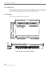
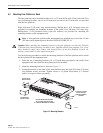
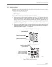
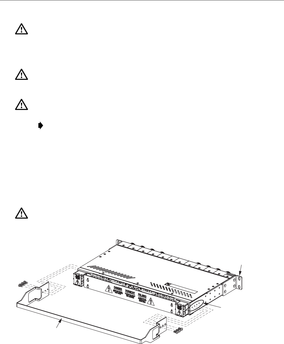
4.1 Installing Cable Management Bar (Optional Item)
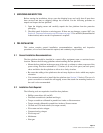
Before installing the fuse platform in the rack, mount the cable management bar (accessory
item) on the rear of the fuse platform as shown in Figure 12. Four 1/4-inch (6.35 mm) long 4-40
screws are provided with the cable management bar. The cable management bar can be recess
mounted by using the mounting holes closest to the front of the fuse platform. Tighten all
screws to 9 pound force-inches (1 Newton-meter) of torque to insure grounding.
Figure 12. Cable Management Bar Installation
Caution: This equipment employs electrical voltage and amperage levels which may be
considered an electrical hazard. Care should be exercised to assure that only qualified
personnel are allowed to install, operate, maintain, or otherwise come in contact with this
equipment when the fuse platform is energized. Only insulated tools should be used on
energized elements of the fuse platform.
Warning: Never install telephone equipment in a wet location or during a lightning storm.
When installing or modifying telephone lines, disconnect lines at the network interface before
working with uninsulated lines or terminals to prevent electrical shock.
Warning: Do not install fuses in fuse platform or power source until you have completed the
power wiring connections.
Note: Do not apply power to the fuse platform until all testing and wiring are completed.
Caution: When attaching the cable management bar to the fuse platform, use only the 1/4-inch
(6.350 mm) long 4-40 screws that are supplied with the cable management bar. Use of any other
hardware could cause contact with internal parts of the fuse platform.
18863-A
CABLE
MANAGEMENT
BAR
ATTACH TO
EITHER SET
OF 3 HOLES
MOUNTING BRACKET
INSTALLED FOR
19-IN. (48.26 CM)
RACK MOUNTING