ADCP-80-526 • Issue 6 • December 2006
Page 15
© 2006, ADC Telecommunications, Inc.
3. Re-install the fuse holder (with working fuse).
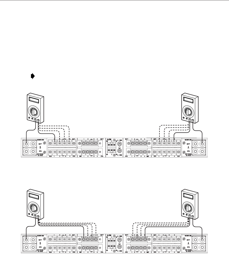
4. Connect one test probe to the BATT (–) terminal on the input power terminal block.
5. Connect the other test probe to the BATT terminal on the output power terminal block.
6. Verify that continuity exists between the specified terminals.
7. Repeat the test procedure for the second fuse type, if present.
8. Repeat the test procedure for the second power bus, if present.
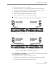
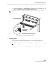
Figure 8. Test 2: Input Battery to Output Battery (Type 1 Fuse)
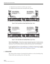
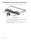
Figure 9. Test 2: Input Battery to Output Battery (Type 2 Fuse)
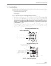
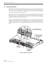
Test 3: Input Return to Output Return—Do the following test for each input power position
and fuse type (refer to Figure 10 and Figure 11).
1. Connect one test probe to the input power RTN (+) terminal
2. Connect the other test probe to the RTN terminal on the output power terminal block.
3. Verify that continuity exists between the specified terminals.
Note: When done, remove the working fuse from the fuse holder following completion of
this test and reinstall an empty fuse holder in each fuse holder position.
18872-A
TEST 2- POWER BUS B:
VERIFY THAT CONTINUITY
EXISTS BETWEEN INPUT
AND TYPE 1 FUSED OUTPUT
BATT TERMINALS
TEST 2- POWER BUS A:
VERIFY THAT CONTINUITY
EXISTS BETWEEN INPUT
AND TYPE 1 FUSED OUTPUT
BATT TERMINALS
TEST 3- POWER BUS B:
VERIFY THAT CONTINUITY
EXISTS BETWEEN INPUT
AND TYPE 2 FUSED OUTPUT
BATT TERMINALS
TEST 3- POWER BUS A:
VERIFY THAT CONTINUITY
EXISTS BETWEEN INPUT
AND TYPE 2 FUSED OUTPUT
BATT TERMINALS
18873-A


