


Chapter 7. Circuit and Network Redundancy
7-4 MX2800 STS-1 User Manual 61200659L1-1
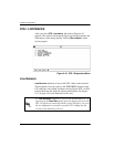
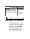
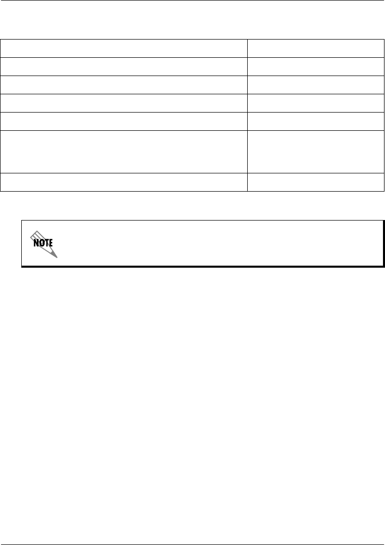
Table 7-1. Configuration Requirements for Circuit Recovery
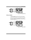
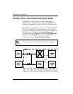
CIRCUIT AND NETWORK FAILURE RECOVERY MODE
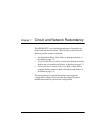
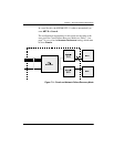
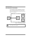
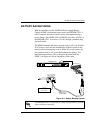
In this mode, two controller cards are installed and connected to
two individual STS-1 lines. This is, of course, the most complete
mode of redundancy. In this mode, the primary controller card is
connected to the primary STS-1 line and the secondary controller
card is connected to the secondary STS-1 line. The primary card
and line actively transmit data, while the other card and line stand
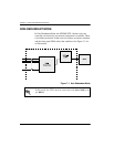
by ready to take over if the first card and line fail. For example, if
C
ARD
A
fails, then control switches to
C
ARD
B
and
NET B
.
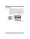
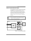
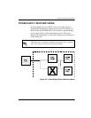
An important feature of the MX2800 STS-1 is its ability to
internally re-route the network connection if a controller card and
the opposite network connection fail. For example, in the
illustration given in Figure 7-3, failed
NET A
is connected to
healthy
C
ARD
A
; and healthy
NET B
is connected to failed
C
ARD
B
.
Selection Path Recommended Setting
Config > Network Interface > XCV Threshold 1E-3 (see the following note)
Config > Network Interface > Network Protection Disabled
Config > Network Interface > Max. Switch Threshold 3
Config > Network Interface > Min. Switching Period 10 seconds
Config > T1/E1 Interface > T1/E1 Circuit Protection Enable all or select the
T1/E1s that redundant
switching should occur on.
Config > T1/E1 Interface > XCV Threshold 1E-3 (see the following note)
The XCV Threshold settings are based on the error rates
considered acceptable on the STS-1 or DS-1 before switching.