


Chapter 2. Installation and Operation
61200659L1-1 MX2800 User Manual 2-3
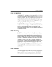
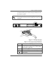
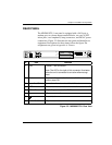
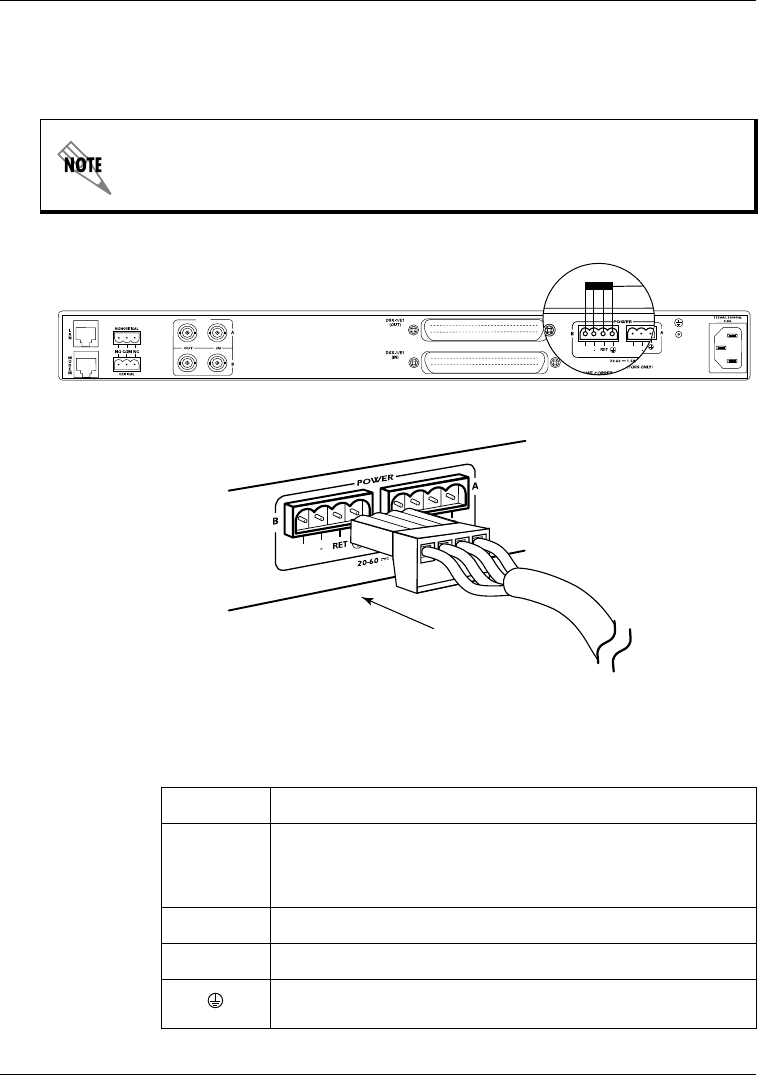
2-3 illustrate the DC power connector and give definitions for the
four connector symbols.
Figure 2-1. DC Power Connector
Table 2-1. DC Connector Symbol Definitions
The chassis should be connected to an earth ground using the
ground stud located between the AC and DC power sources on the
rear panel.
PWR
FAIL
PWR
FAIL
PWR
FAIL
NET
Symbol Definition
PWR FAIL
Battery backup connection. If AC fails, a trap is sent to
alert user when connected to the 4175043L2 battery
backup system or equivalent
- Negative side of DC power source (usually -48V)
RET Positive side of DC power source (usually ground)
Frame Ground