


61202.086L1-1 ISU 512 User Manual 89
Appendix D
Pinouts
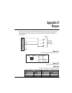
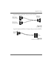
Figure D-1 illustrates the EIA-232 to DB-25 adapter connector. Figures D-2
through D-4 show the interfaces for the pinouts identified in Tables D-A
through D-F.
Figure D-1
EIA-232 to DB-25 Adapter Connector
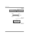
Figure D-2
RJ-45 ISDN Line Interface
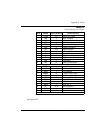
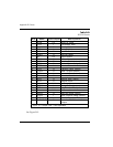
Table D-A
Pinouts for Chain In and Chain Out Ports
1
2
3
4
5
6
7
8
7
2
3
RS-232
DB Style
Connector
RS-232
ISDN
PIN 1 PIN 8
Pin 4 Ring
Pin 5 Tip
For U Interface:
For ST Interface:
Pin 3,6 Transmit pair
Pin 4,5 Receive pair
Chain In Port Chain Out Port
Pin 1 Ground Pin 1 Ground
Pin 3 Rx Data Pin 3 Chain Rx Data
Pin 5 Tx Data Pin 5 Chain Tx Data