


Chapter 3: Installation
12 ISU 512 User Manual 61202.086L1-1
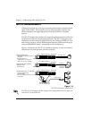
THE MAINTENANCE INTERFACE
The Maintenance Interface is available at 9600 bps, 8 data bits, no parity,
through the CHAIN IN port. See the appendix Pinouts for the Chain In port
pinout. The VT 100 terminal or null modem can be connected to the Chain In
port using the RJ-45 to DB-25 adapter (part number 3196.ADPT003) and the
RJ-45 to RJ-45 cable provided with the unit. The port contains transmit and re-
ceive data (EIA-232 compatible). This interface can be used to set internal S-
registers, dial ISDN connections, and disconnect calls. This port also allows
ADTRAN Technical Support personnel to retrieve vital information from the
unit if a problem is encountered during initial configuration of the ISU 512.
Most problems can be solved without resorting to this port for assistance.
The terminal should be set for 9600 bps, 8 data bits, and no parity. The main-
tenance port is activated by typing !V at the - - 512-> prompt.
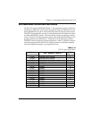
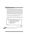
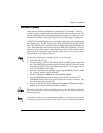
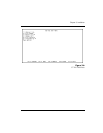
There are four maintenance port commands available to display and clear the
status buffer, display the internal print buffer, loop status and help screen; see
Figure 3-1.
Figure 3-1
Maintenance Port VT 100 Menu
Plugging the RJ-45 cable from the telephone service provider into the Chain In or
Chain Out ports could cause damage to the ISU 512.