


61202.086L1-1 ISU 512 User Manual
9
Chapter 3
Installation
INSTALLATION
After unpacking the unit, immediately inspect it for possible shipping dam-
age. If damage is discovered, file a claim immediately with the shipping car-
rier, then contact ADTRAN Customer Service; see the inside back cover of this
manual for phone numbers.
NETWORK CONNECTION
The ISU 512 (U interface) supports either
Dial
or
Leased
operation. The ISU
512 (ST interface) supports only
Dial
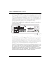
operation. Four 8-pin RJ-45 modular
jacks on the rear panel of the ISU 512 allow connection to either network ser-
vice.
Dial
operation uses the ISDN Basic Rate interface and allows the ISU 512 to
dial out over the ISDN network. When used in this mode of operation, the
telephone company provided ISDN Basic Rate interface is connected to the RJ-
45 connectors marked
ISDN IFC #1
,
#2
,
#3
,
and #4
.
Connect the Basic Rate in-
terfaces to the ISU 512 in order, starting with
ISDN IFC #1
, until the maximum
number of lines (four) is reached.
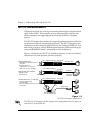
The
Leased
mode of operation supports a dedicated 2B1Q data service at rates
of up to 512 kbps by using nailed up circuits or a permanent connection be-
tween end points. This could be a limited distance modem or point-to-point
connection.
See the appendix
Pinouts
for network connection pin assignments.