


Chapter 3: Installation
10 ISU 512 User Manual 61202.086L1-1
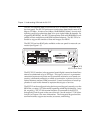
DTE DATA CONNECTION
Data terminal equipment (DTE) is connected to the ISU 512 by using the V.35
interface, and/or the RS-530 interface on the rear panel of the ISU 512. The
maximum cable lengths recommended are 50 feet for the RS-530 interface, or
150 feet for the V.35 interface. The pin assignments for the DTE interfaces are
shown in the appendix Pinouts.
The RS-530 interface and the V.35 interface support data rates up to 512 kbps.
The DTE rate can be configured from the front panel or the VT 100 terminal
interface of the ISU 512. See the chapter Configuration for information regard-
ing configuring the ISU 512 with the appropriate data rates for the application.
To prevent possible radio frequency interference emissions, shielded cables are re-
quired.
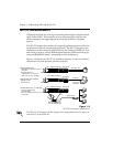
DIAL INTERFACE CONNECTION
If out-of-band RS-366 dialing is required for applications such as video confer-
encing, the dialing interface of the host DTE should be connected to the port
labeled RS366 DIALING PORT. A special RS-366 Y cable provides the two
RS-366 interfaces required for dual-port videoconferencing applications (part
number 1200120L1). For pin assignment information for the RS-366 connector
and the RS-366 Y cable, see the appendix Pinouts.
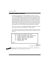
Smart Dial String Formats
The ISU 512 accepts changes to Call Type and Channel Rate by using suffix
commands appended to the end of the dial string. The following string format
is used.
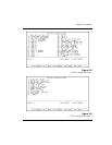
Where #C changes the Call Type as follows:
1 = Speech
2 = Audio
3 = 56K Data
4 = 64K Data
XXX XXX XXXX #C #R
dial string
call type
channel rate