


Appendix C. Network Pinouts
C-4
TSU 120 User Manual 61202129L1-1
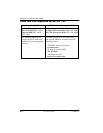
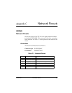
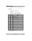
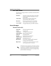
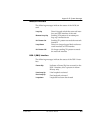
Nx56/64 DTE (V.35)
See Tab le C-4 for the V.35 pinout Nx56/64 DTE pinout.
Connections
The DTE interface pinout is as follows:
Connector type V. 35
Part number AMP# 92-4883-3-x
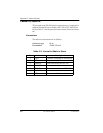
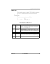
Table C-4. V.35 Pinout - Nx56/64 DTE
*(ignored by TSU 120)
Pin Name Description
A 101 Protective ground (PG)
B 102 Signal ground (SG)
C 105 Request to send (RTS) from DTE
D 106 Clear to send (CTS) to DTE
E 107 Data set ready (DSR) to DTE
F 109 Received line signal detector (DCD) to DTE
L, J — Local Loopback (LL)*
N, BB — Remote loopback (RL)*
R 104 Received data (RD-A) to DTE
T 104 Received data (RD-B) to DTE
V 115 RX clock (RC-A) to DTE
X 115 RX clock (RC-B) to DTE
P 103 Transmitted data (TD-A) from DTE
S 103 Transmitted data (TD-B) from DTE
Y114TX clock (TC-A)
AA 114 TX clock (TC-B)
U 113 External TX clock (ETC-A) from DTE
W 113 External TX clock (ETC-B) from DTE
NN, K — Test mode (TM) to DTE