


TA 544 User Manual/61200704L1-1A
Page 15 of 68
© 2001, ADTRAN, Inc. TA 544 User Manual
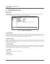
5. INSTALLATION
Unpack and Inspect the Unit
After unpacking the unit, inspect it for possible shipping damage. If the equipment has been damaged in transit, im-
mediately file a claim with the carrier, then contact ADTRAN Customer Service.
Shipped by ADTRAN
The following items are included in the ADTRAN shipment:
• The TA 544
•DB-9adapter
• 6 ft. RJ-45 to RJ-45 cable
• 2 wall mount hinges
• 4 each 6-32 screws
• AC power cord
• CD containing User Manual
Provided by Customer
The following items must be supplied by the customer:
• Cables and connectors used for your application
• Screws to mount the TA 544 to the wall (if applicable)
Mount the Unit
1. Use a #2 Phillips-head screwdriver to insert the 4 each 6-32 screws (all screws are provided with the unit) to
secure the bracket to the unit.
2. Use an appropriate screw (wood/metal) (provided by the user) to secure the unit to the wall.
3. Plug the unit into a grounded outlet.
Double pole/neutral fusing.