


Chapter 1 Hardware Configuration
9
1.6 Jumper Settings
This section tells how to set the jumpers to configure your card. It
gives the card default configuration and your options for each jumper.
After you set the jumpers and install the card, you will also need to
run the BIOS Setup program (discussed in Chapter 3) to configure the
serial port addresses, floppy/hard disk drive types and system operat-
ing parameters. Connections, such as hard disk cables, appear in
Chapter 2.
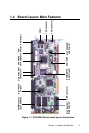
For the locations of each jumper, see the board layout diagram
depicted earlier in this chapter.
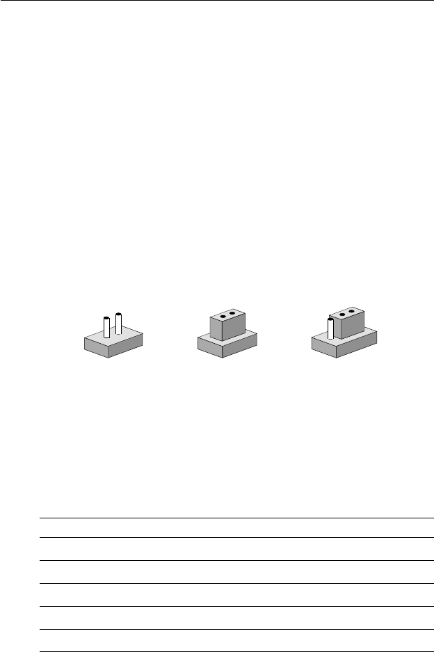
You configure your card to match the needs of your application by
setting jumpers. A jumper is a metal bridge that closes an electrical
circuit. It consists of two metal pins and a small metal cap (often
protected by a plastic cover) that slides over the pins to connect them.
To "close" a jumper you connect the pins with the cap. To "open" a
jumper you remove the cap. Sometimes a jumper will have three pins,
labeled 1, 2 and 3. In this case you connect either pins 1 and 2 or 2 and
3.
You may find a pair of needle-nose pliers useful for setting the
jumpers.
If you have any doubts about the best hardware configuration for your
application, contact your local distributor or sales representative
before you make any changes.
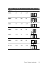
Table 1-1: Jumpers
Label Function
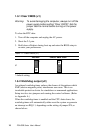
J1 CMOS clear
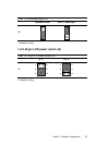
J2 Watchdog timer output
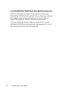
J3 DiskOnChip
®
2000 address setting
J4 44-pin LCD power select (Reserved)
OpenOpen
OpenOpen
Open
1
3
2
ClosedClosed
ClosedClosed
Closed
Closed 2-3Closed 2-3
Closed 2-3Closed 2-3
Closed 2-3