


Figures
Figure 1-1: Front view of the PPC-A84 .................................................................... 7
Figure 1-2: Dimensions of the PPC-A84 ................................................................... 8
Figure 1-3: Dimensions of cutout and panel mounting holes ................................... 9
Figure 1-4: Panel mounting...................................................................................... 10
Figure 1-5: Mounting with universal arm (I) .............................................................11
Figure 1-6: Mounting with universal arm (II) ........................................................... 12
Figure 1-7: Mounting with universal arm (III) .......................................................... 12
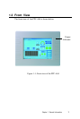
Figure 2-1: Front view of the panel PC................................................................... 14
Figure 2-2: Top side view of the panel PC.............................................................. 15
Figure 2-3: Rear view of the panel PC ................................................................... 16
Figure 2-4: I/O section of the panel PC ................................................................... 17
Figure 2-5: Install or remove the power supply,HDD drive,PCACIA module.......... 18
Figure 3-1: Locating jumpers and connectors PCM-5821 (front side) .................. 39
Figure 3-2: Locating jumpers and connectors PCM-5821 (rear side) ................... 40
Figure 8-1: Setup program initial screen................................................................. 88
Figure 8-2: CMOS setup screen ............................................................................. 89
Figure 8-3: BIOS features setup screen ................................................................ 91
Figure 8-4: Chipset features setup screen ............................................................ 94
Figure 8-5: Power Management setup screen ....................................................... 95
Figure 8-6: PNP/PCI configuration setup screen .................................................... 97
Figure 8-7: Load BIOS defaults screen .................................................................. 98
Figure 8-8: Integrated peripherals screen .............................................................. 99
Figure 8-9: Save and exit setup screen ............................................................... 103
Figure B-1: Disassembly steps 1 - 4 ..................................................................... 111
Figure B-2: Disassembly steps 5 - 7 .....................................................................113
Figure B-3: Disassembly steps 8 - 12 ...................................................................115