


20
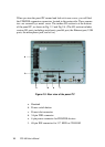
PPC-A84 User's Manual
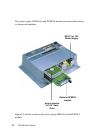
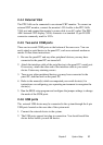
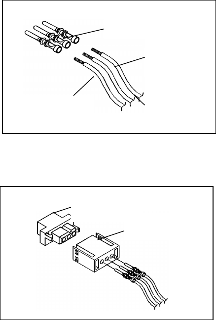
2.3.2 Connecting the insulator to your power sources
There are three male contact pins, three female contact pins and a pair of
insulators in the accessory box. The installation procedure is described as
follows:
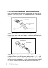
STEP 1. Connect the three contact pins individually to the negative and
positive power cables of the power adaptor, as well as to the frame ground
cable. Solder firmly.
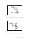
STEP 2. Align the soldered pins and their cables with the corresponding
polarization marks on the front part of the male insulator (+ / G / -). Now
plug the pins separately into the holes of the male insulator. Pin 1 should go
into the positive DC power input ( + ), pin 2 connects to the frame ground (
G ), and pin 3 should be plugged into the negative DC power input ( - ).
3 contact pins
Positive power
cable
Negative power
cable
Frame ground
+
G
_
Female insulator
+
G
¡
—
Male insulator
-
+