


1-108
Making Measurements
Using Test Sequencing
The TESTSET I/O bits are set using the and keys
under the keys. The values of the outputs (pins 11, 22, and 23)
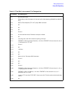
are described in Table 1-5. The value changes with the test port, so if the external control
is required for both test port directions, the settings must be made under both
and . This capability can be used to set different
external conditions in a test requiring changes between the forward and reverse
measurements, as might be needed in a high power test, for example.
TTL I/O Menu
This menu can be accessed by pressing in the Sequencing menu.
TTL Output for Controlling Peripherals Eight TTL compatible output lines can be
used for controlling equipment connected to the parallel port. By pressing ,
you will access the following softkeys that control the individual output bits. Refer to
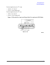
Figure 1-78 for output bus pin locations.
lets you input a number (0 to 255) in base 10 and outputs it to
the bus as binary.
lets you set a single bit (0 − 7) to high on the output bus.
lets you set a single bit (0 − 7) to low on the output bus.
TTL Input Decision Making Five TTL compatible input lines can be used for decision
making in test sequencing. For example, if a test fixture is connected to the parallel port
and has a micro switch that needs to be activated in order to proceed with a measurement,
you can construct your test sequence so that it checks the TTL state of the input line
corresponding to the switch. Depending on whether the line is high or low, you can jump to
another sequence. To access these decision making functions, press . Refer
to Figure 1-78 for input bus pin locations.
lets you select the single bit (0 − 4) that the sequence will
be looking for.
lets you jump to another sequence if the single input bit you
selected is in a high state.
lets you jump to another sequence if the single input bit you
selected is in a low state.
Pin assignments:
• pin 1 is the data strobe
• pin 16 selects the printer
• pin 17 resets the printer
• pins 18-25 are ground
TESTSET I/O FWD
TESTSET I/O REV
Seq
TTL I/O
TTL OUT
TESTSET I/O FWD
TESTSET I/O REV
TTL I/O
Seq
TTL I/O
PARALLEL OUT ALL
SET BIT
CLEAR BIT
Seq
TTL I/O
PARALL IN BIT NUMBER
PARALL IN IF BIT H
PARALL IN IF BIT L