


6-18
Calibrating for Increased Measurement Accuracy
Frequency Response and Isolation Error Corrections
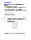
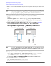
7. Make a "thru" connection between the points where you will connect your device under
test.
NOTE Include any adapters that you will have in the device measurement. That is,
connect the standard device to the particular connector where you will
connect your device under test.
8. To measure the standard, when the displayed trace has settled, press:
The analyzer displays WAIT - MEASURING CAL STANDARD during the standard
measurement. The analyzer underlines the softkey after it measures the
calibration standard, and computes the error coefficients.
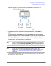
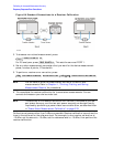
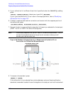
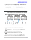
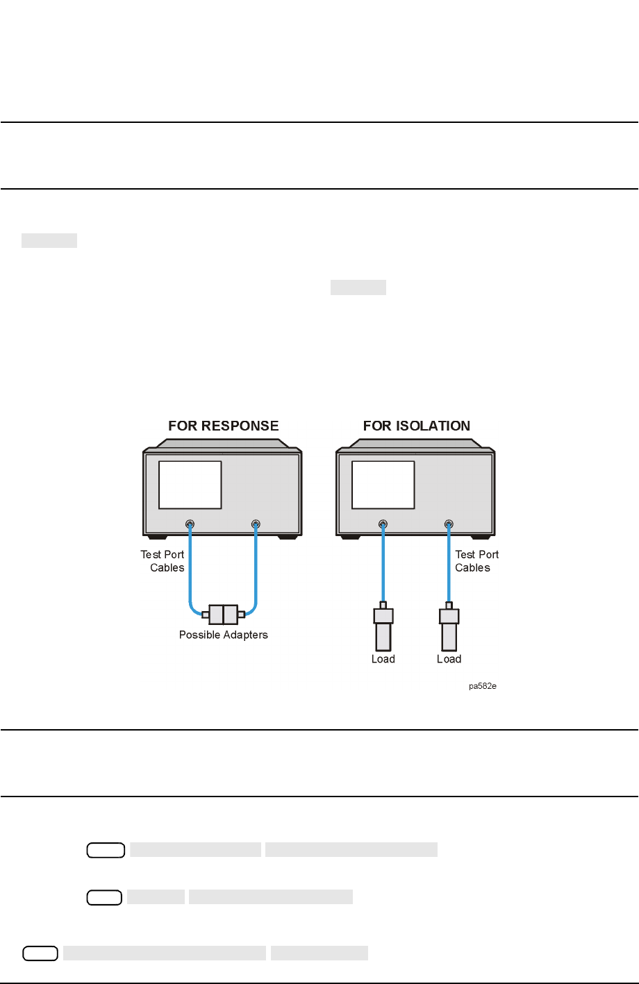
9. Connect impedance-matched loads to PORT 1 and PORT 2, as shown in Figure 6-5.
Include the adapters that you would include for your device measurement.
Figure 6-5 Standard Connections for a Response and Isolation Error
Correction for Transmission Measurements
NOTE If you will be measuring highly reflective devices, such as filters, use the test
device, connected to the reference plane and terminated with a load, for the
isolation standard.
10.To help remove crosstalk noise, set the analyzer as follows:
a. Press and enter at least four
times more averages than desired during the device measurement.
b. Press to eliminate one crosstalk path.
11.To measure the calibration standard, press:
THRU
THRU
Avg
AVERAGING ON
AVERAGING FACTOR
Cal
MORE
ALTERNATE A and B
Cal
RESUME CAL SEQUENCE
ISOL’N STD