


7-74
Operating Concepts
TRL*/LRM* Calibration (ES Models Only)
Fabricating and defining calibration standards for TRL/LRM
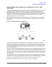
When calibrating a network analyzer, the actual calibration standards must have known
physical characteristics. For the reflect standard, these characteristics include the offset in
electrical delay (seconds) and the loss (ohms/second of delay). The characteristic
impedance, , is not used in the calculations in that it is determined by the line
standard. The reflection coefficient magnitude should optimally be 1.0, but need not be
known since the same reflection coefficient magnitude must be applied to both ports.
The thru standard may be a zero-length or known length of transmission line. The value of
length must be converted to electrical delay, just like that done for the reflect standard.
The loss term must also be specified.
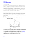
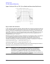
The line standard must meet specific frequency related criteria, in conjunction with the
length used by the thru standard. In particular, the insertion phase of the line must not be
the same as the thru. The optimal line length is 1/4 wavelength (90 degrees) relative to a
zero length thru at the center frequency of interest, and between 20 and 160 degrees of
phase difference over the frequency range of interest. (Note: these phase values can be
±N × 180 degrees where N is an integer.) If two lines are used (LRL), the difference in
electrical length of the two lines should meet these optimal conditions. Measurement
uncertainty will increase significantly when the insertion phase nears zero or is an integer
multiple of 180 degrees, and this condition is not recommended.
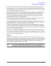
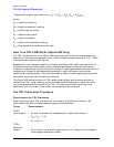
For a transmission media that exhibits linear phase over the frequency range of interest,
the following expression can be used to determine a suitable line length of one-quarter
wavelength at the center frequency (which equals the sum of the start frequency and stop
frequency divided by 2):
let:
f1 = 1000 MHz
f2 = 2000 MHz
VF = Velocity Factor = 1 (for this example)
Thus, the length to initially check is 5 cm.
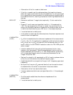
Next, use the following to verify the insertion phase at f1 and f2:
OFFSET Z0
Electrical length cm()
LINE
0 length THRU
–()=
Electrical length cm()
15000
VF
×()
f1 MHz()f2 MHz()+
---------------------------------------------------=
Phase degrees()
360 f× l×()
v
-----------------------------=