


7-49
Operating Concepts
Measurement Calibration
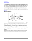
NOTE It is very important that the exact electrical length of the thru be known.
Most calibration kits assume a zero length thru. For some connection types
such as Type-N, this implies one male and one female port. If the test system
requires a non-zero length thru, for example, one with two male test ports,
the exact electrical delay of the thru adapter must be used to modify the
built-in calibration kit definition of the thru.
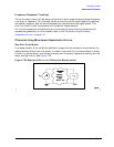
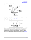
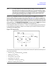
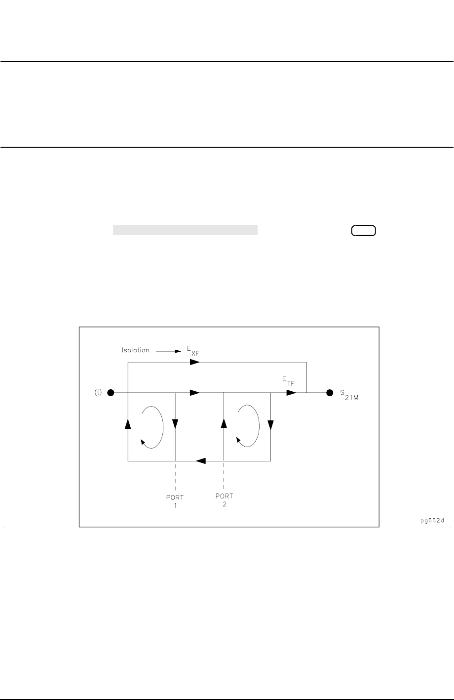
Isolation, E
XF
, represents the part of the incident signal that appears at the receiver
without actually passing through the test device. See Figure 7-37. Isolation is measured
with the test set in the transmission configuration and with terminations installed at the
points where the test device will be connected. Since isolation can be lower than the noise
floor, it is best to increase averaging by at least a factor of four during the isolation portion
of the calibration. The softkey under the menu allows a
calibration sequence to resume after a change to the averaging factor.
If the leakage falls below the noise floor, it is best to increase averaging before calibration.
In this case, omitting isolation is better than measuring the isolation standards without
increasing the averaging factor.
Figure 7-37 Isolation E
XF
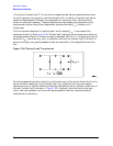
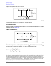
Thus there are two sets of error terms, forward and reverse, with each set consisting of six
error terms, as follows:
• Directivity, E
DF
(forward) and E
DR
(reverse)
• Isolation, E
XF
and E
XR
• Source Match, E
SF
and E
SR
• Load Match, E
LF
and E
LR
• Transmission Tracking, E
TF
and E
TR
• Reflection Tracking, E
RF
and E
RR
RESUME CAL SEQUENCE
Cal