


1-110
Making Measurements
Using Test Sequencing
Test Set Interconnect Control
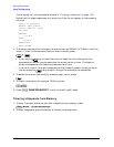
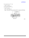
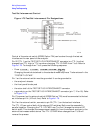
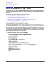
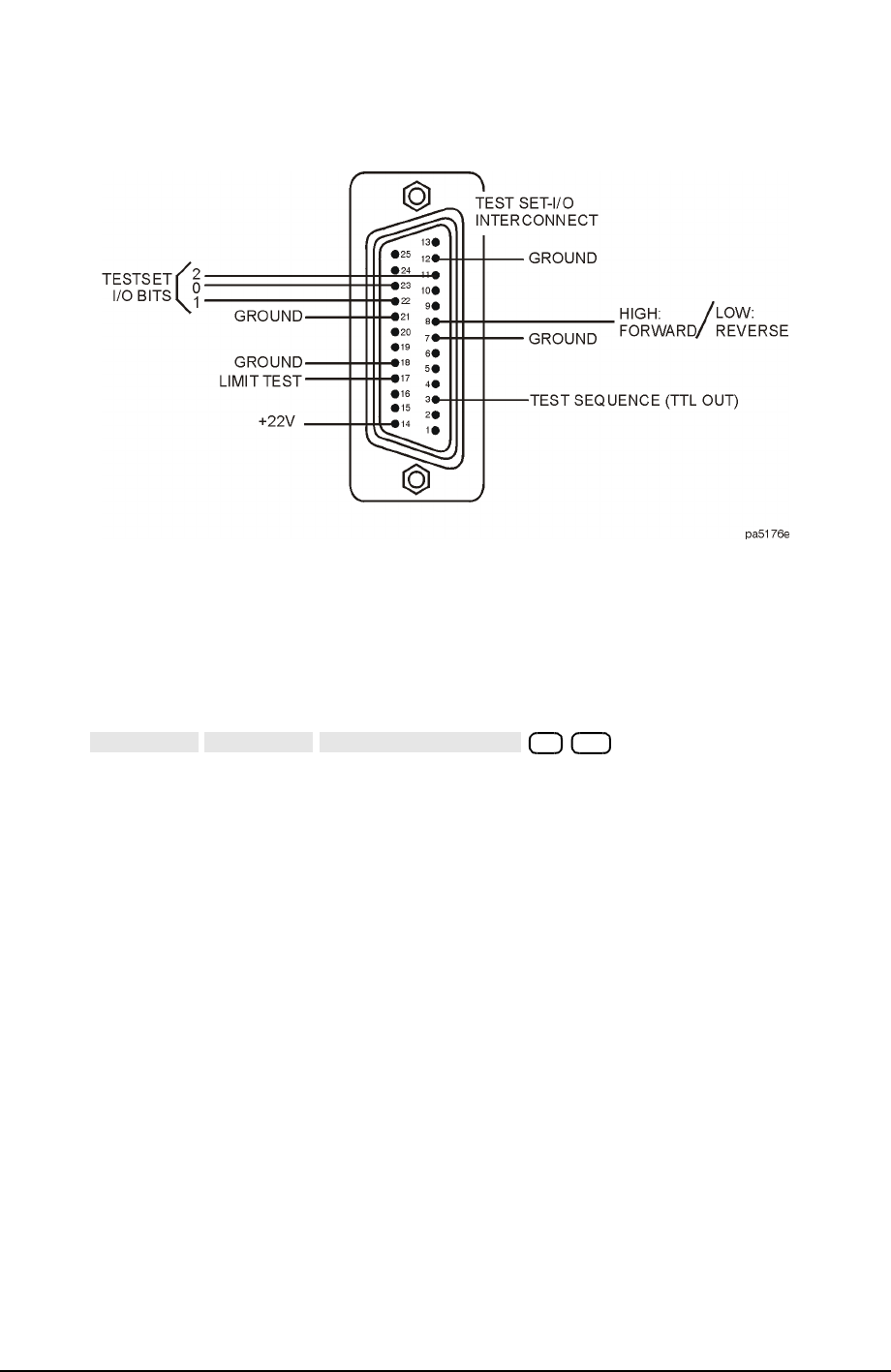
Figure 1-79 Test Set Interconnect Pin Designations
Control of the external switch (8762B Option T24) can be done through the test set
interface on the rear panel of the analyzer.
Pin 22 (TTL 1) on the TEST SET-I/O INTERCONNECT connector is a TTL line that
changes from TTL high to TTL low when changing TTL I/O FWD from 7 to 6. Refer to
Figure 1-79. To change from 7 to 6, press the following sequence:
• Press .
Changing the switch state back to the standard mode requires a 7 to be entered in the
“TESTSET I/O FWD.”
Pin 1 on the external switch must be grounded. It can be grounded to:
• the analyzer's chassis
• the front panel binder post
• the outer shell of the TEST SET-I/O INTERCONNECT connector
• a ground pin on the TEST SET-I/O INTERCONNECT connector (pin 7, 12 or 18). Refer
to Figure 1-79.
Pin C (common) on the external switch (8762B Option T24) must be connected to the test
set interface pin 14 (+22 volt line). Refer to Figure 1-79.
Pin 2 on the external switch, connects to pin 22 (TTL 1) on the test set interface.
The TTL I/O can control both of the external RF switches. Both must be cascaded in
parallel together. Changing the TTL I/O FWD from 7 to 6 will change the external RF
switch state. This changes the measurement capability from the network analyzer to the
external test measurement device. The TTL I/O FWD when changed from 7 to 6 will
reverse the process.
TTL I/O
TTL OUT
TESTSET I/O FWD
6 x1