Command Summary
107
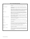
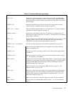
Table C-l. Command Summary (continued)
Command Description
OCP? < ch > Queries the overcurrent protection circuit on/off status for the specified output
channel (see page 72). Response is either a 1 (on) or a 0 (off). The OCP ENBLD
annunciator on the front panel displays the on/off status of the OCP circuit for the
selected output.
*OCRST < ch > Returns the specified output channel to the previous settings after it had been
turned off by the overcurrent protection circuit (see page 72).
* OUT < ch > , < on/off > Turns the specified output channel on or off. On/off equals 1 to turn the output on
and equals 0 to turn the output off (see page 71).
DCPON < on/off > Sets the state of the outputs at power-on. For on/off = 0, all outputs will be off
when the power supply is turned on. For on/off = 1 all outputs will be on when the
power supply is turned on.
OUT? < ch > Queries whether the specified output channel is turned on or off (see page 71). The
response is either 1 (on) or O (off). The front panel will display the message
’’DISABLED’’ when the selected output channel is turned off.
*OVSET < ch >, < overvoltage > Sets the overvoltage trip point for the specified output channel (see page 71).
OVCAL < ch > Causes the specified output channel to go through the overvoltage calibration
routine (see Appendix A).
*OVRST < ch > Attempts to reset the overvoltage crowbar circuit in the specified output channel
(see page 71).
*OVSET? < ch > Queries the present overvoltage setting of the specified output channel (see page
71). The response is a real number.
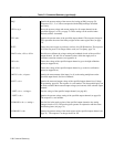
PON < on/off > Enables power on service request (SRQ). On/off equals 1 causes the power supply
to generate a service request when power is applied (see page 77). On/off equals 0
disables the PON SRQ. The on/off setting is retained in the supply’s memory
through interruption of ac line power.
PON? Queries the present state of the power on SRQ function (see page 77). The
response is either 1 (on) or 0 (off).
*RCL < reg > Recalls the voltage and current settings for all output channels from the specified
internal register (1 to 10). These settings were previously stored using the STO
command. RCL programs all output channels in sequential order (1, 2, 3, 4) to
these stored settings (see page 72).
ROM? Queries the revision date of the power supply’s firmware. See Service Manual.
SRQ < setting > Sets the causes for generating SRQ. Setting can be 0, 1, 2, or 3 as described on
page 76.
* Indicates that the command can be executed from the front panel.


