Getting Started 35
Table 3-1. Controls and Indicators (continued)
Number
Controls/lndicators
Description
Page
8
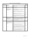
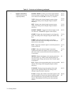
Numeric Entry Keys
(These keys are used in
conjunction with many of the
System Control and Output
Control keys to enter the
desired values into the power
supply.
0 to 9 - Set the value of the specified function
and
(e.g. VSET 16.550)
←
(backspace) - Erases the previous keystroke. Depressing
this key without setting a value places the display in the
metering mode.
ENTER- Enters the values on the display for the specified
function, initiates the function, and returns the display to
the metering mode. Pressing this key without setting a
value will result in retention of the previous values and
returning the display to the metering mode.
37, 83,
84
83
37, 83,
84
9
LINE Switch
Turns ac power on and off.
37
Normal Self Test Indications
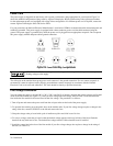
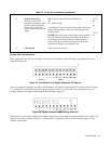
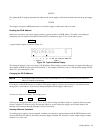
If the supply passes the self test, the display will first show all segments of the LCD display with annunciators on as
illustrated in Figure 3-2.
Figure 3-2. Test Pattern of all Display Segments at Power-on
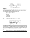
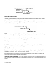
After all segments are displayed, the supply’s GP-IB address will appear for approximately 2 seconds as shown in Figure
3-3. As shipped from the factory, the power supply’s address is set to 5. You must know this address before you can
remotely program your supply (see Reading the GP-IB Address, page 39).
Figure 3-3. Typical Address Display During Power-On
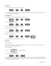
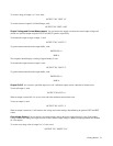
When self test is successfully completed, the output voltage and current readings (both approximately 0) for output 1 will
appear in the display as shown in Figure 3-4. Note that the CV annunciator will also indicate that the output is in the
constant voltage mode.


