Programming with a Series 200/300 Computer
103
CC Operation
Programming for CC operation is straightforward. Program each output to the desired voltage limit point. Then program
each output to supply half of the total desired operating current. Both outputs will operate in CC mode. Note that the total
desired current cannot exceed the combined current capability of both outputs. Figures 4-11 and 4-12 are examples of
parallel configurations. These configurations apply to both CV and CC operating modes. Note the sense lead connections.
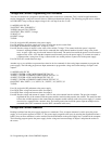
10 ASSIGN @Ps TO 705
20 INPUT "ENTER VOLTAGE LIMIT’’,V
30 INPUT "ENTER OPERATING CURRENT",Oc
40 C = Oc/2
50 OUTPUT @Ps;"CLR;VSET1,’’;V;";ISET1,";C;";VSET2,";V;";ISET2,";C
60 END
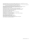
LINE 10: Assigns the I/O pathname to the power supply.
LINE 20,30: Enter the voltage limit and operating current.
LINE 40: Divides the total current requirement by 2.
LINE 50: Clears the supply and sets each output to supply half of the desired operating current at any voltage up to the
desired voltage limit.
CV Operation
For CV operation, one output must operate in CC mode and the other output must operate in CV mode. The output that is
operating in CV mode will be controlling the voltage regulation of both outputs.
In the example that follows, outputs 1 and 2 (both 40 W or 80 W Low V channels) will be operating in parallel with output
1 in CV mode and output 2 in CC mode at output voltages above 2.5 V. Each is programmed to one half of the desired
current limit point. Above 2.5 V, the voltage for output 2 is always programmed higher than that of output 1 to ensure that
output 2 operates in the CC mode. Note that any current from output 2 that is not required by the load flows into the
downprogrammer of output 1 and is reflected in the current readback of output 1. The total current supplied to the load can
be read back by adding the results of reading back the currents of outputs 1 and 2. At 2.5 V and below, the outputs are set to
the same voltage and the operating modes depend upon the load.
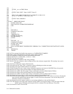
10 ASSIGN @Ps to 705
20 INPUT "ENTER OPERATING VOLTAGE",V1
30 INPUT "ENTER TOTAL CURRENT LIMIT",Ilim
40 C = Ilim/2
50 IF V1 > 7 THEN V2 = 20.2
60 IF V1< =7 THEN V2=7.07
70 IF Vl < = 2.5 THEN V2 = V1
80 OUTPUT @Ps;"CLR;ISET1,";C;";VSET1,";V1
90 OUTPUT @Ps;’’ISET2,";C;"VSET2,";V2
100 WAIT 1
110 OUTPUT @Ps;"VOUT?1"
120 ENTER @Ps;Vout
130 OUTPUT @Ps;"IOUT?1’’
140 ENTER @Ps;Ioutl
150 OUTPUT @Ps;"IOUT?2"
160 ENTER @Ps;Iout2
170 PRINT "OUTPUT VOLTAGE IS ";Vout
180 PRINT "TOTAL OUTPUT CURRENT IS ";Ioutl + Iout2
190 END


