Remote Operation 70
Range Switching
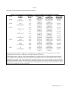
Each output operates in the boundaries of either the low range or the high range as specified in Table 5-4. Refer to page 43
for a detailed description of the dual range operation. The range is selected based on the programmed parameters. If the last
parameter (voltage or current) programmed is outside of the existing range, the supply will automatically switch ranges. A
sequence of examples are given on the next page to illustrate this operation. Output 1, used in the examples, is a 40 W Low
V output.
Example 1: VSET 1,5; ISET 1,2
This example programs output 1 to 5 V and 2 A. These values are in the quadrant of the characteristic curve which has
voltage and current boundaries common to both high and low operating ranges.
Example 2: VSET 1,20
Now output 1 is in the high range programmed to 20 V and 2A.
Example 3: VSET 1,5; ISET 1,3
Output 1 is now in the low range programmed to 5 V and 3A.
Example 4: VSET 1,10
Now output 1 is in the high range and the current is automatically scaled back from 3 A to the lower current limit of
2.06 A. The output is operating in the same range as that of Example 2.
Example 5: VSET 1,20; ISET 1,3
The ISET command will cause the voltage to be scaled back to the low range limit of 7.07 V and the output will operate
within the boundaries of the low range as in Example 3.
NOTE When the range is automatically switched, as in examples 4 and 5, the "coupled parameter’’ bit (CP) in the
status register (see Table 5-5) is set to indicate that range switching occurred.
Output On/Off
The OUT command disables/enables an output channel of the power supply. It will not disturb any other programmed
function nor will it reset the protection circuits. You can control individual outputs with the OUT command as shown
below. For example, to disable output channel 1 send the following:
OUT 1,0
To enable output channel 1 send the following command
OUT 1,1
You can find out the present state of output 1 by sending the query:
OUT? 1
and addressing the supply to talk. The response from the supply is either a "0" to indicate output 1 is off or a "1’’ to indicate
that the output is on. When disabled, the output behaves as if it were programmed to zero volts and minimum
current.


