Calibration Procedures94
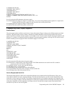
470 !
480 IF FNPs _ err < >0 THEN Finish
490 !
500 OUTPUT @Ps;"VSET ";Chan,"0 ;ISET ’’;Chan,"0"
510 !
520 INPUT "ANY MORE OUTPUTS TO CALIBRATE? (Y OR N)",X$
530 IF (X$=’’Y" OR X$=’’y") THEN Start_loop
540 !
550 OUTPUT @Ps;"CMODE 0"
560 !
570 Finish: ! HERE WHEN DONE
580 OUTPUT @Ps;’’CLR"
590 DISP "END OF CALIBRATION PROGRAM"
600 END
610 !
620 !
630 DEF FNDvm
640 COM /Instr/ (@Ps,@Vm
650 WAIT.02
660 TRIGGER @Vm
670 ENTER @Vm;Reading
680 RETURN Reading
690 FNEND
700 !
710 DEF FNPs _ err
720 COM /Instr/ @Ps,@Vrn
730 OUTPUT @Ps;’’ERR?"
740 ENTER @Ps;Err
750 IF Err< >0 THEN PRINT "POWER SUPPLY ERROR # '';Err;" CORRECTION CONSTANTS NOT SAVED -
RESTART. "
760 RETURN Err
770 FNEND
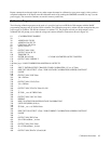
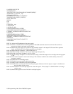
LINE 10: This comment line identifies the program as a CALIBRATION EXAMPLE.
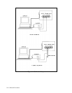
LINE 30,40: Assigns I/O path names to the power supply and the voltmeter.
LINE 50: Establishes a COM block for the instruments on the GP-IB.
LINE 60: Initializes the variable Shunt _ resistor to .1 ohms.
LINE 80: Clears the power supply.
LINE 90: Initializes the voltmeter to take voltage readings.
LINE 100,110: Tells the voltmeter to take a reading and clears the voltmeters output buffer. This reading is not used in
the program.
LINE 120: Turns on the power supply calibration mode.
LINE 140: Labels the line ''Start_loop" to loop back to when calibrating more than one output.
LINE 160: Enters the output channel number to be calibrated.
LINE 170,180: Prompts the user to make voltage calibration connections and waits for CONTINUE key to be pressed.
LINE 200: Sets the voltage of the specified output to the high calibration point.
LINE 210: Sets the variable Vhi to the output voltage as measured by the user defined function FNDvm.
LINE 230: Sets the voltage of the specified output to the low calibration point.
LINE 240: Sets the variable Vlo to the output voltage as measured by the user defined function FNDvm.
LINE 260: Sends the measured data in volts to the power supply for the specified channel.
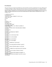
LINE 280: Checks the power supply for errors with the user defined function FNPs _ err. If there was an error, the program
goes to the line labeled Finish and the supply is cleared. The new measured data is not used and the previous
calibration constants are maintained.
LINE 300: Instructs the power supply to perform an overvoltage calibration on the specified channel.
LINE 310--330: Displays a message on the computer until bit 4 (RDY) of the power supply's serial poll register indicates
that the supply is finished processing the OVCAL command. This may take up to 10 seconds.
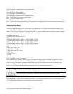
LINE 350: Checks for errors. See line 280.


