


12 Configuring the RF Switch
Chapter 1
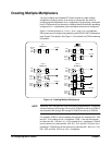
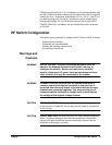
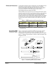
Creating Multiple Multiplexers
You can configure the Cascade RF Switch module to create multiple
multiplexers of varying sizes. In its power-on/reset state, the switch is
configured as 20 independent 3-to-1 multiplexers. By specifying a valid path
from a COM terminal to a channel in a different bank (functionally cascading
contiguous 3-to-1 multiplexers) other multiplexer sizes can be configured.
Figure 1-3 shows typical 3-to-1, 6-to-1, 9-to-1, and 12-to-1 multiplexers.
Other sizes can be configured by specifying valid ROUTe:PATH statements
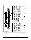
(see Chapter 2 for details). See Figure 1-2 for channel and COM numbering
information.
NOTE Generally, the COM terminal is on the highest-numbered bank. Exceptions
are that channels 100 through 132 can go to COM 05 as well as to COM 13
and channels 300 through 332 can go to COM 25 as well as to COM 33.
For example, COM 01 can be used as the common for channels 000 - 002
and 010 - 012 creating a 6-to-1 multiplexer. COM 11 can be the common
for channels 100 - 102 and 110 - 112 for another 6-to-1 multiplexer. COM 02
can be common for channels 000 - 002, 010 - 012, and 020 - 022 for a 9-to-1
multiplexer. COM 03 can be the common for channels 000 - 002, 010 - 012,
020 - 022, and 030 - 032 for a 12-to-1 multiplexer.
Figure 1-3. Creating Multiple Multiplexers
(BB+1)1
(BB+1)0
(BB+1)2
(BB+2)1
(BB+2)2
(BB+2)0
COM (BB+2)
(BB)1
(BB)0
(BB)2
Channel
(BB)1
(BB)0
(BB)2
9-to-1
Multiplexer
Multiplexer
COM (BB)
3-to-1
(BB+3)2
(BB+3)1
(BB+3)0
(BB+1)0
(BB+1)1
(BB+1)2
(BB+2)0
(BB+2)1
(BB+2)2
COM (BB+3)
(BB)0
(BB)1
(BB)2
(BB)1
(BB)0
(BB)2
(BB+1)1
(BB+1)0
(BB+1)2
12-to-1
Multiplexer
Multiplexer
COM (BB+1)