


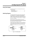
14 Configuring the RF Switch
Chapter 1
Setting the Logical
Address
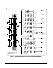
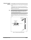
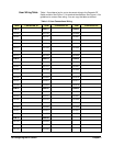
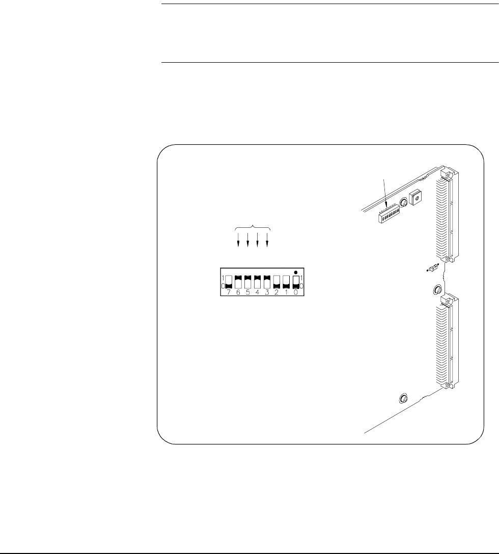
The logical address of the Cascade RF Switch module is set with the Logical
Address (LADDR) switch on the module. The logical address is factory-set
to 120. Valid addresses are from 1 to 256. See Figure 1-4 for address switch
settings.
The logical address is the sum of the values of the switches set to the
CLOSED position. In Figure 1-4, switches 3 through 6 are CLOSED and the
associated values of these switches are 8, 16, 32, and 64. Thus, the logical
address = 8 + 16 + 32 + 64 = 128.
NOTE When using the Cascade RF Switch module with an E1406 Command
Module, the address must be a multiple of 8 (for example, 8, 16, 24,...
112, 120, 128,... 240, 248). The module cannot be configured as part
of a multiple-module switchbox instrument.
If the Logical Address Switches are set for 255, the System Resource
Manager automatically assigns a Logical Address to the module. You can
poll the Resource Manager to determine the logical address assigned to the
module.
Figure 1-4. Setting the Logical Address Switch
Logical Address
Switch Location
Logical Address = 120
CLOSED = Switch Set To 1 (ON)
OPEN = Switch Set To 0 (OFF)
1=CLOSED
0=OPEN
8
1
6
3
2
6
4
1
2
8
2
4
1
64+32+16+8=120