


Register-Based Programming 43
Appendix B
A16 Address Space
Outside the Command
Module
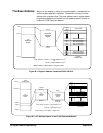
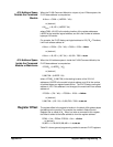
When the E1406 Command Module is not part of your VXIbus system, the
E1470 base address is computed as:
A16
base
=C000
h
+(LADDR
h
*40
h
)
or (decimal)
A16
base
= 49,152 + (LADDR * 64)
where C000
h
(49,152) is the starting location of the register addresses,
LADDR is the module’s logical address, and 64 is the number of address
bytes per VXI device.
For example, the E1470 factory-set logical address is 120 (78
h
). Therefore,
it will have a base address of:
A16
base
= C000
h
+(78
h
*40
h
)=C000
h
+1E00
h
= DE00
h
or (decimal)
A16
base
= 49,152 + (120 * 64) = 49,152 + 7680 = 56,832
A16 Address Space
Inside the Command
Module or Mainframe
When the A16 address space is inside the E1406 Command Module, the
E1470 base address is computed as:
1FC000
h
+ (LADDR
h
*40
h
)
or (decimal)
2,080,768 + (LADDR * 64)
where 1FC000
h
(2,080,768) is the starting location of the VXI A16
addresses, LADDR is the module’s logical address, and 64 is the number
of address bytes per register-based device. The E1470 factory-set logical
address is 120. If this address is not changed, the module will have a base
address of:
1FC000
h
+(78
h
*40
h
) = 1FC000
h
+1E00
h
= 1FDE00
h
or (decimal)
2,080,768 + (120 * 64) = 2,080,768 + 7680 = 2,088,448
Register Offset The register offset is the register’s location in the block of 64 address bytes
that belong to the module. For example, the module’s Status/Control
Register has an offset of 04
h
. When you write a command to this register,
the offset is added to the base address to form the register address:
DE00
h
+04
h
=DE04
h
1FDE00
h
+04
h
= 1FDE04
h
or (decimal)
56,832 + 4 = 56,836 2,088,488 + 4 =
2,088,492
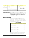
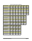
Table B-1 shows general programming method to access E1470 registers.