


Configuring the RF Switch 13
Chapter 1
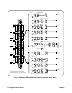
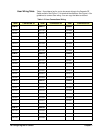
COM 04 can be used for a 15-to-1 multiplexer for all channels between 000
and 042. COM 05 can be the common for all channels from 000 through 052
creating an 18-to-1 multiplexer. Multiplexers of 21-to-1, 24-to-1, and 27-to-1
can also be configured. Two 30-to-1 multiplexers can be created using
channels 00 through 132 to COM 05 and channels 200 through 332 to
COM 25. One 60-to-1 multiplexer can be created using all the channels
to COM 25.
RF Switch Configuration
This section gives guidelines to configure the RF Switch module, including:
• Warnings and Cautions
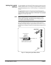
• Selecting the Logical Address
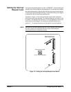
• Setting the Interrupt Request Level
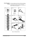
• Connecting User Wiring
Warnings and
Cautions
WARNING SHOCK HAZARD. Only service-trained personnel who are
aware of the hazards involved should install, remove, or
configure the module. Before you remove any installed
module, disconnect AC power from the mainframe and from
other modules that may be connected to the module.
WARNING CHANNEL WIRING INSULATION. All channels that have a
common connection must be insulated so that the user is
protected from electrical shock in the event that two or more
channels are connected together. This means wiring for all
channels must be insulated as though each channel carries
the voltage of the highest voltage channel.
CAUTION MAXIMUM POWER. The maximum RF power that can be applied
to the module is 10 Watts RF. Do not apply line AC power to any terminal
on this module.
CAUTION STATIC ELECTRICITY. Static electricity is a major cause of component
failure. To prevent damage to the electrical components in the module,
observe anti-static techniques whenever removing a module from the
mainframe or working on a module.