


Register-Based Programming 45
Appendix B
CAUTION Registers have been documented as 8-bit bytes. If you access them using
16-bit transfers from a Motorola CPU, the high and low byte will be
swapped. The E1406 uses Motorola CPUs. Motorola CPUs place the
highest weighted byte in the lower memory location and the lower weighted
byte in the higher memory address while Intel processors do just the
opposite. VXI registers are memory-mapped. Thus, you will see this
Motorola/Intel byte swap difference when doing register programming.
Manufacturer
Identification
Register
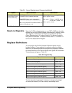
The Manufacturer Identification Register is a read-only register at address
00
h
(Most Significant Byte (MSB)) and 01
h
(Least Significant Byte (LSB)).
Reading this register returns the Hewlett-Packard identification, FFFF
h
.
Device
Identification
Register
The Device Identification Register is a read-only register accessed at
address 02
h
. Reading this register returns the module identification of 581
(245
h
).
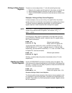
Status/Control
Register
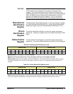
The Card Status/Control Register is a read/write register accessed at
address 04
h
. You read the Status Register and write to the Control Register.
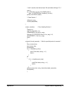
Table B-3. Status Register Bit Patterns (read)
Address b+04
h
Address b+05
h
15 14 13 12 11 10 9 8 7 6 5 4 3 2 1 0
111111CDI0CDI1BSYIEN11111SR
SR (soft Reset): 0 = not in reset, 1 = held in reset state.
IEN: Main interrupt enable. Bit is set to 0 when interrupts are enabled; 1when interrupts are disabled.
BSY: Bit is set to 0 when module is busy - relays are settling. Bit is set to 1 if the module is not busy.
CDI0 and CDI1: When set to 0, indicates the relay assemblies are connected to the driver assembly. CDI0 is the right
hand relay assembly, CDI1 is the left hand assembly. If either bit is set to a 1, the respective relay assembly is not
installed.
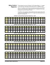
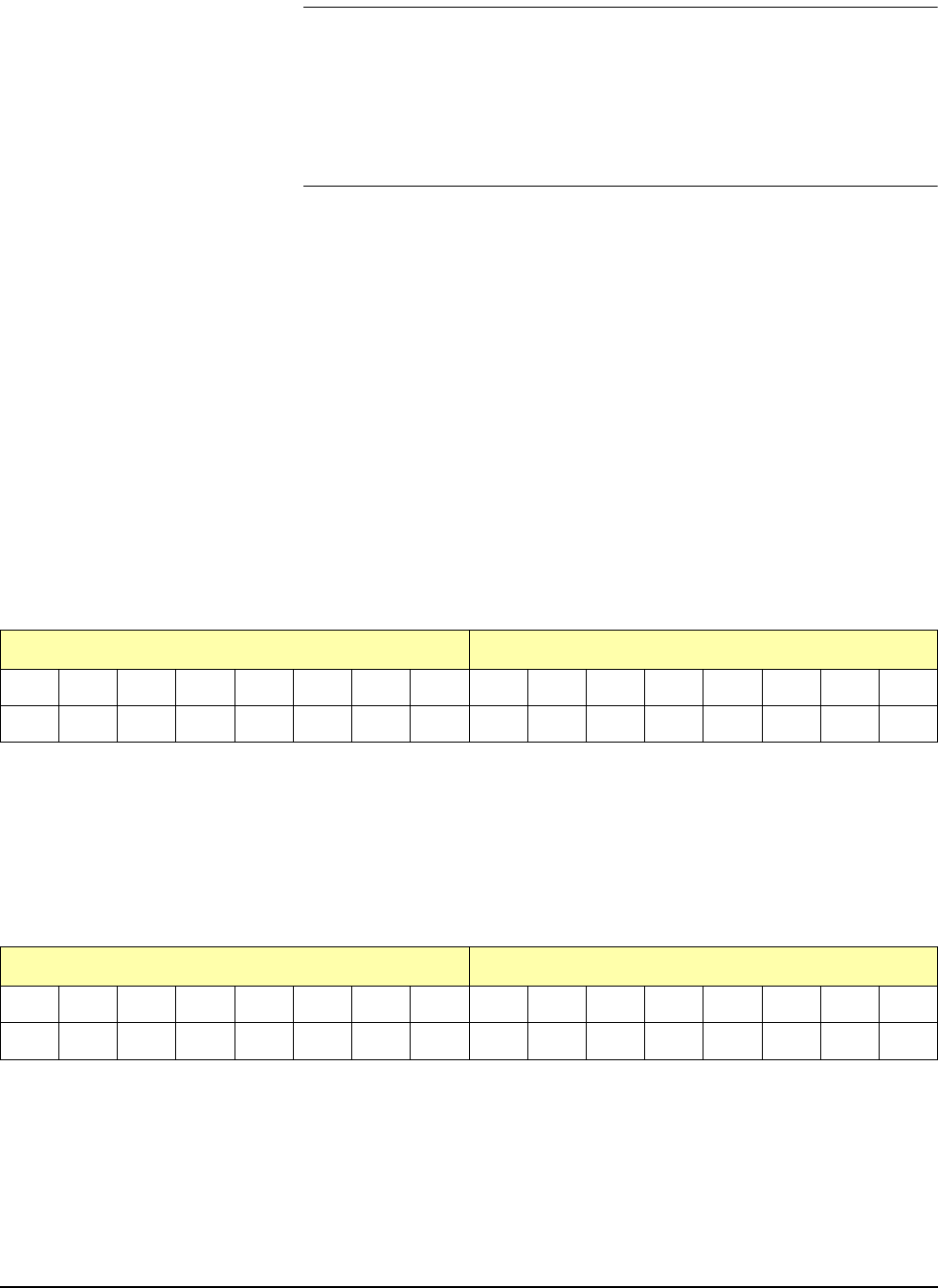
Table B-4. Control Register Bit Pattern (write)
Address b+04
h
Address b+05
h
1514131211109876543210
1 11111111IEN11111SR
SR (soft reset): Writing a “1” and then a “0” to this bit resets all relays on the module to their power-on/reset state.
IEN: Main interrupt enable. Writinga1tothisbitcausesaninterrupttobegenerated16msecafteravalueiswrittentoany
relay control register to indicate that a relay closure should be complete. At power-on/reset, this bit is set to 0.