16 Configuring the RF Switch
Chapter 1
Connecting User
Wiring
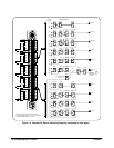
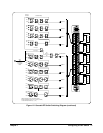
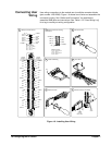
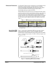
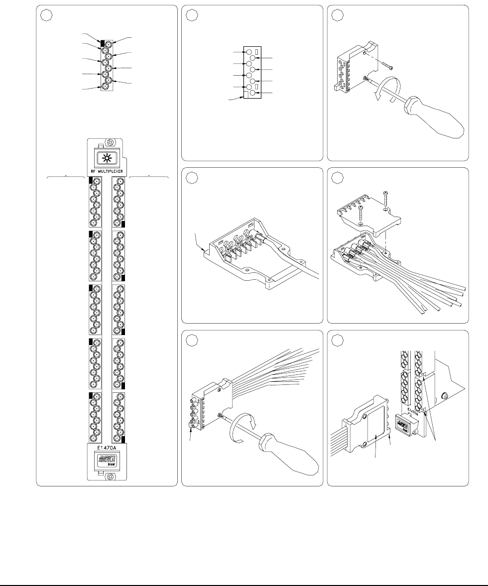
User wiring connections to the module are via multiple connector blocks
(part number 1250-2563). Figure 1-6 shows how to wire and assemble the
connector housing. See “Cables and Connectors” for guidelines to
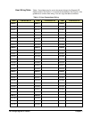
assemble SMB jacks and connectors. See Table 1-2 in “User Wiring Log”
for a log to record your wiring configuration.
Figure 1-6. Installing User Wiring
Identify Connector Housing
20, 21, 22, 23, 24, 25
00, 01, 02, 03, 04, 05
(BB+1)1
230100
122
120
121
COM 12
131
COM13
132
COM 11
130
210
211
212
COM 21
201
202
COM 20
200
COM 22
Key
BB=Bank Number:
20, 21, 22, 23, 24, 25
00, 01, 02, 03, 04, 05
042
041
101
102
040
COM 10
111
112
110
COM 05
052
051
021
022
COM 02
020
COM 04
COM03
050
032
COM 01
030
031
002
001
000
COM 00
011
012
010
Numbers
Channel
30, 31, 32, 33
10, 11, 12, 13
COM(BB+1)
(BB+1)2
Channel
Key
251
252
250
231
232
COM 23
220
222
221
241
242
COM 24
6
312
311
COM 31
310
COM 25
302
240
COM 30
301
300
COM 32
Replace Screws
Channel
Numbers
COM 33
332
331
330
320
321
322
4
(BB)0
Channel
(BB)1
Channel
30, 31, 32, 33
Install Field Wiring
10, 11, 12, 13
BB=Bank Number:
Identify Connector Pinout
Channel
(BB+1)0
Channel
Key
1
COM(BB)
(BB)2
Channel
2
Pinout
Guide
Hole
Key
Key
Install Connectors on Module7
Close Shell5
Remove Screws3
COM(BB+1)
(BB+1)2
(BB+1)1
(BB+1)0
Key
(BB)0
(BB)1
(BB)2
COM(BB)
A Label
Can Be
Placed Here


