


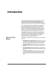

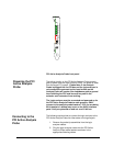

Pod 1 channel 0 can be configured to view any one of the four
PCI interrupts. Move the jumper so that it corresponds to the
desired interrupt and that interrupt line will be routed to POD 1
channel 0. The jumper and interrupt stake pins are clearly
labeled and are located under POD 7.
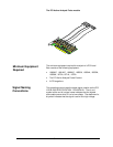
Viewing the
interrupts
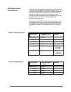
Interrupt Jumper
Pod 0 Channel 1 INT
I I I I
N N N N
T T T T
A B C D
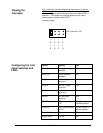
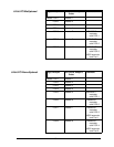
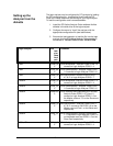
Configuring the front
panel switches and
LEDs
Switch Setting LED
Parity On Parity Checking
enabled
ON
Parity On Parity checking
disabled
OFF
No Wait No Wait cycles
acquired
ON
No Wait All Wait cycles
acquired
OFF
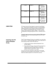
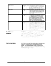
No Idle No Idle cycles
acquired
ON
No Idle All Idle cycles
acquired
YES
TDO/TDI TDO connected to
TDI
No LED, switch in
rightmost position
TDO/TDI TDO not connected
to TDI
No LED, switch in
leftmost position
State/Timing State ON
State/Timing Timing OFF
10