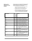
The logic analyzer can be configured for PCI analysis by loading
the PCI configuration file. Loading this file will load the PCI
Local bus inverse assembler and configure your logic analyzer.
To load the configuration and inverse assembler:
Setting up the
Analyzer from the
diskette
1. Install the PCI Active Analysis Probe software flexible
diskette in the disk drive of the logic analyzer.
2. Configure the menu to “Load” the analyzer with the
appropriate configuration file (see table below).
3. Execute the load operation to load the file into the logic
analyzer that the PCI Active Analysis Probe module is
connected to. DO NOT SELECT ALL OR SYSTEM.
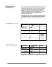
Logic Analyzer File
nam
e for
State
Anal
ysis
Comment
166x P32M_66
0
32 bit Multiplexed - Analysis Probe PODS 1-4
connect to Logic Analyzer PODS 1-4
166x P32D_66
0
32 bit Demultiplexed - Analysis Probe PODS
1-6 connect to Logic Analyzer PODS 1-6
166x P64M_66
0
64-bit Multiplexed- Analysis Probe PODS 1-
4,7,8,11 to Logic Analyzer PODS 1-7
16550A P32M_55
0
32 bit Multiplexed- Analysis Probe PODS 1-4
connect to Logic Analyzer PODS 1-4
16550A P32D_55
0
32 bit Demultiplexed - Analysis Probe PODS
1-6 connect to Logic Analyzer PODS 1-6
16550A P64AD55
0
32 bit address Demultiplexed and 64 bit data
Analysis Probe PODS 1-6,7,8 and 11
connect to Logic Analyzer PODS 1-6 on
the Master card and 1-3 on the Slave card
respectively.
16550A P64M_55
0
64-bit Multiplexed - Analysis Probe PODS 1-
4,7,8,11 connect to LA PODS 1-6 on the
Master card and Pod 1 on the Slave card
respectively
16550A P64D_55
0
64 bit Demultiplexed- Analysis Probe PODS
1-11 connect to Logic Analyzer PODS 1-6
on the Master card and PODS 1-5 on the
Slave Card respectively
1655x,167x P32M_55
5
32 bit Multiplexed - Analysis Probe PODS 1-4
connect to Logic Analyzer PODS 1-4
16


